Cable and Harness Manufacturing:
Protecting your Cable Tester
Revised February 2018
First published in Test & Measurement World magazine November, 2005
Outline
2 - Mechanical HazardsAttachment of a "Live" Cable to the Tester
Static Discharge into Test Point Terminals
Power Line Transients
Conductive Debris
Connector Wearout3 - Component Failure
Defective Connectors
Improper Insertion
Contamination
Improper Storage
4 - Software Failure
Summary
Our dependence on complex systems in modern manufacturing leaves us vulnerable to unexpected process failure that may have expensive consequences. While we cannot foresee the future, our awareness of failure modes should lead to simple preventve measures. Well taken precautions help avoid the silent panic following our realization that a preventable accident will extract a heavy cost in time and inconvenience to correct.
Well taken precautions help avoid the silent panic following our realization that a preventable accident will extract a heavy cost in time and inconvenience to correct.
-C.E.S. CAMI Research
Protecting your Cable Harness Tester
Any action which serves to impair or prevent normal operation of your cable harness tester may have expensive side effects on your business –
- Contract manufacturers may be unable to ship cable products without the required quality certification;
- OEM manufacturers may be unable to certify incoming cable or harness assemblies before commitment to inventory;
- Factory maintenance personnel may be prevented from diagnosing malfunctioning robotic, printing press, or other computer-controlled machinery, causing expensive delays in production.
Disruptive events include both temporary situations like voltage transients, and less easily corrected problems like equipment damage.
Test and quality control engineers may be proactive about preventing process failures by their awareness of potential problems, and development of procedures to prevent failure and speed equipment repair when failure occurs.
We summarize major causes of process failure and suggest actions you may take to minimize their effects.
Electrical Hazards
1 – Attachment of a “Live” Cable to the Tester
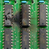
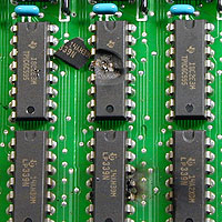
Each of the one-hundred or more test points in a typical cable tester connects directly to an integrated circuit used in applying or measuring test signals. Although various means of overload protection can be built into each point, it becomes economically impractical to isolate the test points from more than a few volts higher than the maximum test voltage. Should the operator inadvertently connect a live cable to the tester, severe damage may ensue. If the overvoltage is considerably above the test voltage, breakdown of the affected IC may transmit the overvoltage through the power bus reaching many interconnected ICs and rendering the circuit board irreparable. ICs may actually explode leaving a blackened crater on the inside of the case as shown in the following photos.
Note: Testing a cable that is connected to a power supply will cause rapid destructive heating which will destroy electronics. Sensible precautions must be employed to prevent this scenario.
Figure 1: Photos of circuitry damaged by attachment of a live cable to a cable tester.
|
Overload Preventive Measures |
|
|---|---|
| a | Do not allow any power sources on the test bench. |
| b | Keep the work area clutter-free and uncrowded. |
| c | Disconnect any unused interface cables from nearby computers or other equipment. |
| d | When testing long cables, ensure that both ends are labeled, and include in the test procedure a positive confirmation that both ends are detached before attaching the cable to the tester. |
| e | Ensure that any batteries that may be attached to the cable, or built into the cable, are disconnected. |
| f | If you test harnesses built into an equipment cabinet, ensure that all conductors and the shield conductor (if tested) are isolated from ground during testing. Ground differential voltage may cause the test to fail or damage the tester. |
2 – Static Discharge into Test Point Terminals
Taking the usual precautions of working on a grounded workbench with dissipative mats, grounding the test equipment, and wearing a wrist strap may be insufficient to protect the tester from static damage. Charge may develop on the insulation of long cables as a result of frictional motion when the operator coils or uncoils the cable while moving it to the test bench. Charge on the insulation then attracts opposite charge on the copper conductors just under the insulation. This in turn forces charge to the cable endpoints where it remains trapped. Refer to the drawing below.
Figure 2: Static Charge Build-Up on Cable Insulation.
The properly grounded operator picks up the cable by its connector, which is insulated from the outer jacket and conductors, and unknowingly discharges the copper conductors into the test equipment at the moment the connector is attached. The volume of charge released may overload clamping diodes built into the tester’s ICs, causing damage to the circuitry. Generally, cables longer than 10 feet (three meters) pose increased risk, especially cables with rubber insulation.
Note: A sufficiently large discharge will overcome any static suppression circuitry that is embedded within the tester. Sensible precautions must be employed to prevent damage to the tester.
|
Static Discharge Preventive Measures |
|
|---|---|
| a | Work with a humidity level of 60% or higher (not usually possible during winter months). |
| b | Equip the tester with transient suppressor boards in which special high-speed Zener diodes protect each point from transients higher than the test voltage and less than ground. |
| c | Attach a grounding plug to the cable momentarily before connecting it to the test equipment. The grounding plug consists of a mating connector in which all pins are connected together and tied with a single wire to an earth ground. |
3 – Power Line Transients
A one second power interruption may disrupt batch testing and cause a loss of log data or batch reports, requiring involvement of a supervisor to restore normal operation, and possibly repeat testing. Power surges and switching noise risk damage to equipment as well as stored data.
|
Power Line Transients Preventive Measures |
|
|---|---|
| a | A 600-1000 watt, pure sine wave uninterruptible power supply (UPS) should be sufficient protection for most workstations, and represents a small fraction of the cost of the equipment it protects (UPS cost is typically less than $150 for the tester alone, or less than $200 for both the tester and computer). Note: Inexpensive UPSs have square wave outputs which will damage switching regulators. |
| b | If your facility provides building-wide uninterruptible power, add a surge suppressor to the testers power input. |
2 – Conductive Debris
Wire clippings, metal punch-outs, metal dust, or spilled beverages may cause unintentional connections between test points, or work their way onto the circuit board and introduce shorts. Coffee and soda are highly conductive when liquid and leave conductive residue when dry, creating a difficult repair problem, especially for testers measuring isolation resistance above one Megohm.
|
Conductive Debris Preventive Measures |
|
|---|---|
| a | Do not permit cable assembly or repair in the vicinity of the test equipment. |
| b | Do not permit food or drink at the test station. |
| c | Place a dust cover over the test equipment when not in use. |
| d | Avoid situating the test equipment in the same room as grinding or metalworking machines. |
Mechanical Hazards
1– Connector Wearout
Natural wear caused by the friction of inserting or removing connectors from mating sockets cannot be avoided. However, some simple precautions will prevent premature failure and quickly restore equipment to proper function.
|
Connector Wearout Preventive Measures |
|
|---|---|
| a | Use connector isolators (trade names: “Connector Protectors”, “Header Isolators”, “Connector Savers”). These small adapters insert between the cable tester and cable connector to absorb the force and wear of repeated insertions. They may be easily unplugged and changed when necessary. Widely available for Dsub connectors. Also available for 64-pin headers. |
| b | Require the mating connectors on your test equipment to have solid metal pins, not stamped pins, and include gold plating. |
2 – Defective Connectors
If the physical characteristics of connectors used on your cables are slightly out of specification, they may deform or in other ways damage the mating connector on your cable tester. For example, plastic RJ45 modular plugs sometimes have excess unremoved flashing from the mold, or sharp edges, which catch the wire pins on sockets. When unplugged from the tester, the wire pins may hang up on the flashing and become bent upon removal, permanently damaging the socket. Note that the same problem may damage your customer’s connectors and you may be held responsible.
|
Defective Connectors Preventive Measures |
|
|---|---|
| Not all connector manufacturers produce quality parts. For generic connectors, like RJ modular plugs, carefully inspect sample parts before committing to a supplier. Require a quality certificate from the supplier before accepting incoming parts. | |
3– Improper Insertion
Test technicians who apply excess force off-axis from insertion direction may bend the pins or shell of a mating connector.
| Improper Insertion Preventive Measures |
|
|---|---|
| a | Situate the cable tester, connector boards, or panel so that the force applied during insertion easily aligns with the connector axis. |
| b | Provide proper training and written procedures for test technicians. |
| c | Ensure that keying marks or other indicators of orientation appear clearly on the mating connectors. |
| d | Some cables have intentionally plugged holes in female connectors to prevent backward insertion. Expressly mark the technician’s work sheet or procedure if hidden orientation keys exist in the test cable. |
4– Contamination
Liquid spillage, including glue, potting compound, or beverages, can permanently damage both the cable tester and device under test. Airborne dust can also build up and cause a tester fault.
Contaminated test fixtures will spread dirt, oils and conductive debris to the header connectors of
the test equipment and vice versa.
Contaminated test fixtures and/or header connectors could lead to false test results (false FAILs) of your product. Because of the risk of cross contamination, we recommend regular maintenance of your test fixtures and header pins following recommendations for protecting your cable tester.
|
Contamination Preventive Measures |
|
|---|---|
| a | Keep the cable assembly area physically separate from the test bench. |
| b | Do not store or permit the use of chemicals, glue, potting compound, or other substances on the test bench. |
| c | Do not permit food or beverages on the test bench. |
| d | Keep the test area dust-free. |
| e | Regularly check and clean any filters that are part of the tester |
| f | Regularly check and clean tester headers and test interface fixtures. |
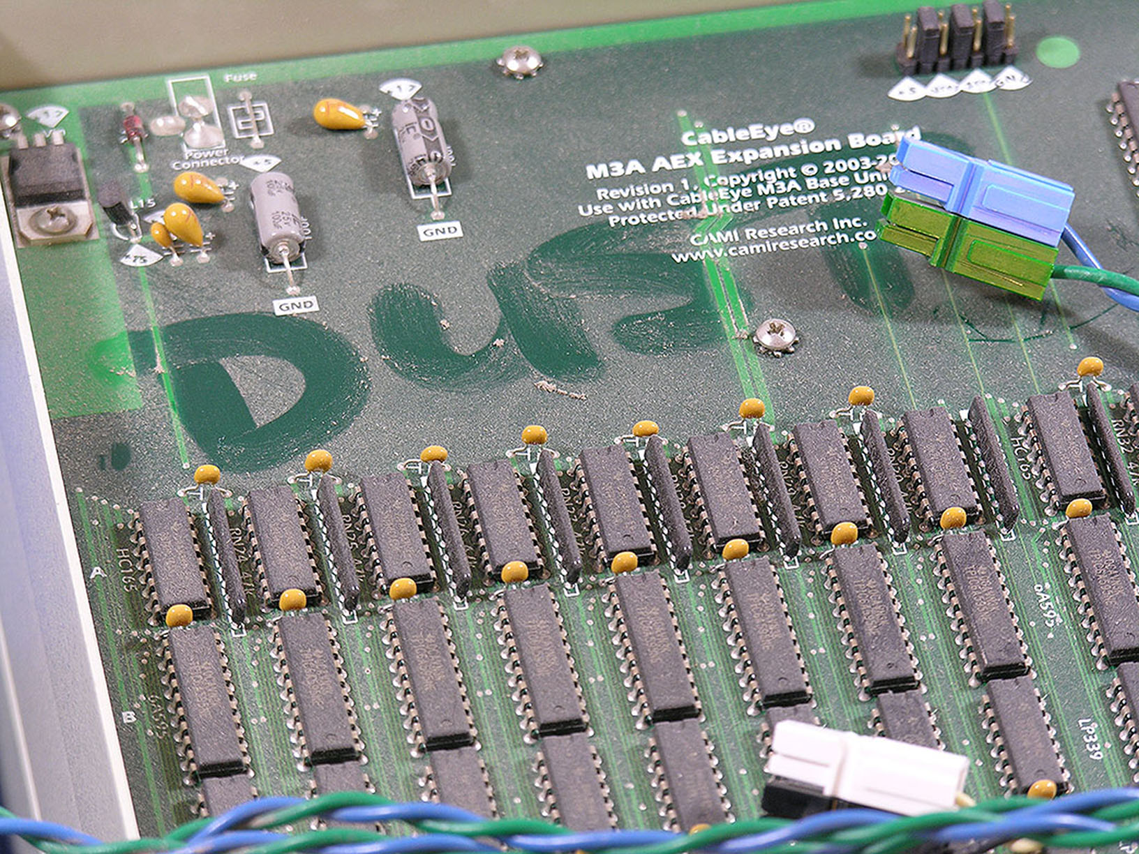
Figure 3: A Dusty Tester Undergoing Service
5– Improper Storage and Packaging
Most cable testers use plug-in connector boards to accommodate many different connector styles. When boards are detached from the tester, connectors may be damaged if not properly stored. An example of recommended storage is shown in photo below (Fig. 4).
Testers that are inadequately packaged to survive the rigors of shipment to the factory for service will likely arrive damaged.
|
Improper Storage and Packaging Preventive Measures |
|
|---|---|
| a | Store boards in a rack so that connectors do not make contact with other boards during storage. |
| b | Use a dust cover over large or fragile connectors, or put boards in bubble bags. |
| c | Store filled racks in closed cabinets. |
| d | Follow factory packaging guidelines for tester storage and shipment. |

Figure 4: Recommended Storage of Test Interface Fixtures
Component Failure
Under normal circumstances, equipment will ultimately fail given enough time and use. The “mean time between failure” statistically predicts how long you can expect normal operation, on average, before failure occurs. While end-of-life wearout cannot be avoided, we need not invite this outcome prematurely.
|
Component Failure Preventive Measures |
|
|---|---|
| a | Turn off computers and test equipment at the end of the work day or when not being used. Fans and other mechanical components wear predictably while operating during periods of disuse, and semiconductors age faster when powered on due to heat and current flow. End-of-day shutdown and beginning-of-day startup may be managed inexpensively and automatically by timers, or network controls, or simply by assigning this job to a specific employee. |
| b | Prevent overheating by providing adequate ventilation including regularly cleaning filters, vacuuming vent holes, and locating equipment away from known heat sources. |
| c | Block unauthorized use by untrained personnel by requiring passwords for computer-controlled equipment and locking power sources when other access controls become impractical. |
Software Failure
Inadvertent erasure of valuable data, malicious action, or internal hardware failure, may expunge critical programs, procedures, scripts, and log files. No other process failure yields as easily to correction, or risks such adverse consequences. As we increasingly rely on computer-controlled equipment, our procedures must reflect data backup as an essential action of no less importance than documentation, labeling, or inspection.
|
Software Failure Preventive Measures |
|
|---|---|
| a | Schedule daily automatic backups of your computers to include cable databases, scripts, log files, and written procedures. Various commercial software offers daily networked backup of specified machines without human intervention. End-of-day backup scripts may include automatic equipment power-down when complete. |
| b | Keep an off-site backup, refreshed weekly or monthly, as appropriate, in the event of catastrophic loss of facility. |
| c | Write-protect data to prevent inadvertent erasure or malicious damage. Establish a log-in procedure for your cable tester software to ensure that ill-trained employees do not learn faulty cable data to force a defective work lot to pass. |
Summary
Our dependance on complex systems in modern manufacturing leaves us vulnerable to unexpected process failure that may have expensive consequences. While we cannot forsee the future, our awareness of failure modes should lead to simple preventive measures. Well taken precautions help avoid the silent panic following our realization that a preventable accident will extract a heavy cost in time and inconvenience to correct.
Our CableEye tester has shown us problems in our systems that we did not even know we had. As a result of finding and addressing these problems, our systems are working better and more reliably than ever before.
E.B.
Vandenberg AFB, CA
Hear more from our customers ...
CableEye ® Automation-Ready Cable and Wire Harness Test Systems
CableEye testers are highly versatile, expandable and upgradable diagnostic and Pass/Fail check Cable and Harness Test Systems that are PC-based. They are used for assembly, prototyping, production, and QC of standard or custom wire cables and harnesses The entire suite of products is powered by the same easy-to-use operating software and, with the help of its signature easy-to-interpret color-coded graphics, instantly identifies not only when there is a fault, but what type of fault and where.
Low Voltage M2 Series
For diagnostic and Pass/Fail Testing - Find, display, log, & document continuity (opens, shorts, miswires, intermittent connections).
Low Voltage M3 Series
For all of the above plus resistance (contact, isolation, embedded), and diodes (orientation, forward voltage, reverse breakdown).
Low Voltage M4 Series
For all of the above plus precision resistance (4-wire), and capacitance (twist wire relationship, length of cable, length to break, capacitors).
Low Voltage and High Voltage HVX Series
For all as described for M3 plus HiPot (dielectric withstand voltage and insulation resistance). 4-Wire Kelvin Measurement and Advanced Measurement Options (capacitance, twist wire relationship, length of cable, length to break, capacitors) are available.
Try One!
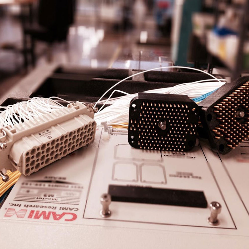
photo credit: Progressive Image
photo credit: AP Technology
"Our production guys find it simple to setup and use. Our clients love it as it provides complete traceability for each and every cable assembly we manufacture."
AP Technology, UK