Ten Single-Pole Double-Throw Relays for External Digital Control
Not Compatible with M2Z or M2U-Basic
Stackable except when used with model M2U


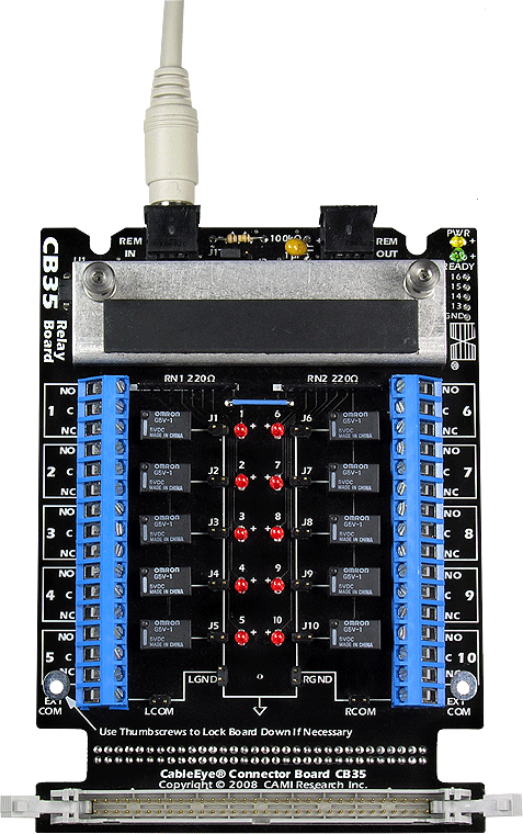
Ten independently-controlled SPDT relays with dry contacts allow program control of circuits or control elements associated with the unit under test. Issue Macro or JavaScript commands to close or open a relay coil, then perform the desired test. Alternatively, you may close different circuits depending on the outcome of a test. For example, illuminate a bin where a failed cable should be placed, or illuminate different bins to show locations for devices sorted by resistance or resistance tolerance. Use a relay to trigger a visual or audible signal indicating the end of a batch, or for a marking device to emboss test results on the wire or connector body.
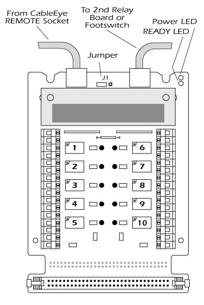
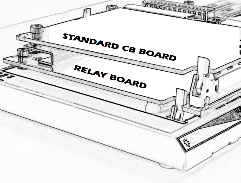
The relay board includes a small cable that connects the board to the Remote Control socket on the back of the machine; this provides power and control signals from the tester. The board uses no test points. Nonetheless, it can be attached to either Bank 1 or Bank 2 by plugging directly into the control module's 64-pin header. Special brackets allow a standard CB board to be mounted above the relay board/s to operate in the normal manner using all 64 pins in that bank position (see drawing below). Relay boards can be stacked in all but the M2U.
For HVX-series testers, attach the CB35 to a riser board (Item 755A) or set elsewhere on the bench. The CB35 must be used in this detached mode when test voltages exceed 250 V.
Each relay coil has an associated LED lamp which turns on when the coil activates. This helps when debugging Macros during setup and test of the manufacturing procedure. The terminal block provides three output terminals for each relay: Common, Normally Open, and Normally Closed. The jumper configuration on the board lets you leave all relay common terminals floating, tie the common terminals together linked to an external common, or tie the common terminals to the local signal ground.
The screw terminal blocks accept 12- to 30-gauge bare wires and have 5 mm (0.197”) spacing between the contacts. The board may also be supplied without terminals for special customer-mounted connectors (contact us for details).
The relay board is sold as a single board, not a board set, and is NOT compatible with the M2Z or M2U-basic. Each board includes a control cable that links to the control module. With the exception of the M2U, multiple relay boards may be used at the same time. The relays operate at +5 V and derive power from the tester which is capable of supplying two relay boards. An external +5 V supply is required for more than two boards. Independent Power and Ready LEDs show the status of the board.
Relay Specifications
| CB35 | CB35H | |
|---|---|---|
| Relay Type | Omron G5V-1 or Equivalent | Omron HY1-5V or Equivalent |
| Contact Load | 0.5 A at 125 Vac, 1 A at 24 Vdc | 0.5 A at 125 Vac, 1 A at 30 Vdc |
| Contact Resistance | 100 mΩ max | 100 mΩ max |
| Bounce Time | 0.2ms (operate), 5ms (release) | 0.2ms (operate), 4 ms (release) |
| Insulation Resistance | 1000 MΩ min | 1000 MΩ min |
| Dielectric Strength | 400 Vac, 50/60 Hz between contacts | 500 Vac, 50/60 Hz between contacts |
1 Single board.
CB35/H 64-Pin Headers are rated for operation up to 250 Vdc/ac. Note this is not the operational voltage of the relays.
Can be certified for operation at the maximum rated voltage for a service fee (Item 626).

