Table of ContentsOverview |
OverviewOur latest Windows™ software for the CableEye® PC-based cable tester makes it easier than ever to test, document, and label cables of all kinds. The familiar Windows interface lets users measure a cable in less than one second, view a graphic wiring display of the cable's schematic, add descriptive notes, and save cable data in a searchable database for future reference.
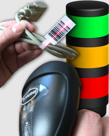
The unique, patented CableEye software makes it the only cable tester available that can generate live, dynamic color cable wiring graphics automatically from continuity measurements, easily showing the location of faults. Publication-quality wiring schematics may be used for documentation, bid submissions, and quality-control reports, greatly assisting ISO9000-certified companies. The software may be set up for automatic operation by unskilled operators. By pressing one button or scanning a bar code, the operator will trigger a sequence that checks a cable, prints a serialized label, outputs documentation, and logs the test result to a batch record on disk. The test time, error rate, operator name, and average time to test are also stored. This ensures repeatable, traceable testing. |
The software has user-set, multi-language navigation - translated by native speakers: Chinese, English, French, German, Hebrew, Italian, Japanese, Korean, Polish, Spanish, Turkish, Ukranian. Synthetic speech can be activated when a matching generic voice font has been downloaded.
CableEye software may easily be used with touchscreen laptop and notebook PCs for field testing.
The software, as described above, comes with all testers at no extra charge. Optional add-on software is also available for purchase that enables guided assembly; fixture mapping; connector graphic creation of unusual connectors; use of the software without the tester; an Applications Programming Interface and more.
Speech recognition is available for the optional guided assembly add-on software permitting the technician to speak wire codes to the system, thus eliminating the need for a keyboard or monitor.
Examples given below that require optional software are indicated as "An Add-On Option". |
||
|
|
||||
Display Modes
Next Topic | Previous Topic | TOC
Most screenshots on this page are of the CableEye software in Control Mode and with English selected as the screen language. This Control Mode is the view that the CableEye Test System Manager uses to access all system options and to program the tester.
There is also a Production Mode that displays only a limited set of essential controls and information to the production worker and which can be activated with a single click or barcode reader.
Additionally, the CableEye Test System Manager can program the tester to display a pop-up window with detailed operator Work Instructions containing text, photos, interactive buttons, and triggers to open additional resources such as video, schematics, parts lists and BOMs. The Work Instructions display can be programmed to fill the screen, and to let barcode readers input data and activate tests. You can choose the exact amount of detail, imagery, language and automation you need to ensure your work instructions and tests are carried out flawlessly.
Production Mode
Next Topic | Previous Topic | TOC
The Production Mode displays only a limited set of essential controls and information to the production worker and which can be activated with a single click, or barcode reader. Use of a touch screen and/or barcode reader allows the production bench to be free of keyboard and mouse. A screenshot example of this Production Mode Screen is shown below.
Additionally, the CableEye Test System Manager can program the tester to display a pop-up window with detailed operator Work Instructions containing text, photos, interactive buttons, and triggers to open additional resources such as video, schematics, parts lists and BOMs. The Work Instructions Display can be programmed to fill the screen, and to let barcode readers input data and activate tests. You can choose the exact amount of detail, imagery, language and automation you need to ensure your work instructions and tests are carried out flawlessly.
A screenshot of the Production Mode is shown here. Most other screenshots on this page are of the CableEye software in Control Mode and with English selected as the screen language.

Control Mode
Next Topic | Previous Topic | TOC
The left side of this Control Mode screen image (below) shows summary representations of the cable under test and the match cable to which it is compared (grey boxes). In this case, a straight-through DB15HD female-to-male cable was measured ("Test Data"), and we are comparing it to a DB15HD male-to-female cable with complex wiring ("Match Data"). Note that the test data (top blue screen) is not shielded and its wiring is quite different. You may highlight a particular wire path for study if desired, as shown in the Match Data window below.
Descriptive notes about the Match Data cable appear in an editable window in the lower left part of the screen. Each cable stored in the database includes separate fields for descriptive notes and label text. If a cable will not fit in the window shown, click the "expand" button (an "X" with arrowheads on each corner) for a full-screen wiring display.
Most screenshots on this page are of the CableEye software in Control Mode and with English selected as the screen language.
Comparing Two Cables
Next Topic | Previous Topic | TOC
When Test Data and Match Data compare perfectly, there are no differences between cables, and we judge the device under test as "good". The lower window in this screen shot shows a DB15HD male-to-male direct extension.
We set the upper window in this case to show the differences between Test and Match data by pressing the Delta button (small triangle, see the tool bar along the top of the screen). Because the cables are identical, we see the message Cables Match, No Differences.
In this case, there is a short circuit between pins 3 and 13 on the left side of the cable, and missing connections on the right side. The difference list indicates missing connections (opens) with a "-" highlighted in yellow, and extra connections (shorts) with a "+" highlighted in red.
Measuring Diodes, Checking LED Color
Next Topic | Previous Topic | TOC
CableEye testers automatically detect diodes embedded in a cable when you test or learn a new cable. Simple diode connections are drawn using the standard diode symbol while complex diode networks appear listed in a floating window above the schematic. Miswired diodes or diodes with incorrect polarity are detected immediately (standard with all models). Excluding M2-series models, all testers will also measure the diode's forward voltage as shown in the screenshot.
LEDs are diodes. They emit color that is dependent on the forward voltage. CableEye testers can check the color of an
LED by checking that forward voltage. An LED of an incorrect color will be highlighted as a miswire.
Measuring Resistors (All CableEye Models excluding M2 series)
Next Topic | Previous Topic | TOC
Measure embedded resistors or resistor networks within a cable, wiring harness, or backplane. In this case, the 120 Ω resistor in the test data agrees with the position and value of the resistor stored in the Match Data (not shown), and a "PASS" indicator appears (yellow check in green box). Choose the tolerance you wish in the Resistance Preferences panel before measurement so that insignificant variations in value will be accepted.
Highlight the resistor in the Test Data window, as shown below, and see the measured value in the Group Netlist popup window. Click the "Ω" button to remeasure the resistance of that line, or the "continuous" button (circulating arrows) to continually remeasure the resistance while you look for bad connections or adjust a potentiometer.
Detecting Resistance Errors
(All CableEye Models excluding M2-series)
Next Topic | Previous Topic | TOC
When resistance errors are found during testing, the Wiring Differences net list shows by how much the resistance differs from your specification. In this case, the cable should have all conductors below the low threshold of 10 Ω (current thresholds appear in the message bar along the bottom of the screen).
One conductor exceeds that limit at 11 Ω. Highlight the affected wire and click the "Ω" button to retest just that wire.
Detecting Intermittent Faults
Next Topic | Previous Topic | TOC
CableEye software offers two methods to check for intermittent connections; one detects continuity differences only (opens/shorts) and another detects and reports resistance variations.
There are two methods of reporting resistance variations:
- 2-Wire (not available for the M2 series)
- 4-Wire resistance measurements (requires Model M4 or an HVX series tester fitted with 4-Wire option).
The Continuity Only Test offers the fastest scan rate and is standard on all tester models.
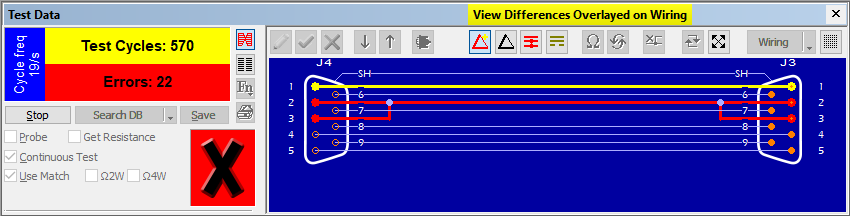
When the test runs, a tone will sound if any faults are found, the error count will increment, and a wiring diagram will display with all accumulated intermittent connections highlighted. The highlighted wires indicate the conductors whose continuity or resistance changed during the test.
In this following example (see screenshot), we see that an intermittent short between pins 2 and 3 and an intermittent open between 1 and 1 were detected. With 19 full test cycles being completed every second, in 570 test cycles, 22 error events were detected. Click the Print icon to save the results as a PDF or to send to the printer.
Measuring Capacitance
(CableEye Models M4, and HVX-series models fitted with Advanced Measurements Option)
Next Topic | Previous Topic | TOC
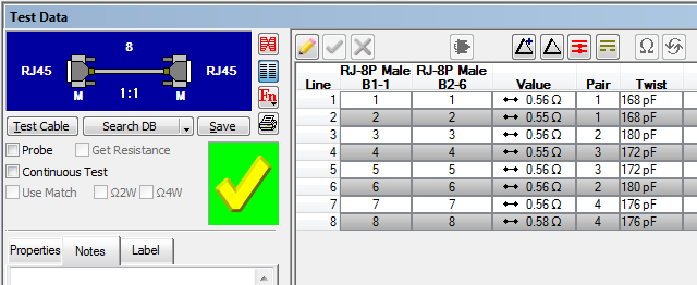
Measure polarized and unpolarized capacitors, capacitance between wires, distance to break, length of cable, and twist pairing.
Measuring Insulation Quality (HVX-series models)
Next Topic | Previous Topic | TOC
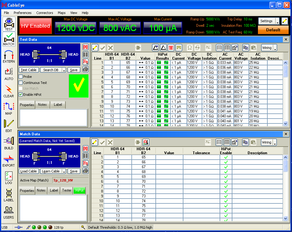
Measure dielectric strength, insulation resistance, and leakage, to check the quality of insulation of your UUT including checking for presence of contaminants. An indicator panel at the top of the CableEye control screen shows the present hipot settings. One test cycle can include any combination of a Fast DC Test, Full DC Test, and AC Test. Additional columns may be turned on in the net list to show actual DC voltage, DC current, DC isolation, AC voltage, AC current, and AC isolation. You may test AC at 60 or 50 Hz.
Netlist Display
Next Topic | Previous Topic | TOC
To view details of the wiring connections, use the Netlist Display instead of the graphic wiring display. This shows the wire connections, resistance threshold, electrical reference numbers, wire colors, and descriptions for each wire.
Creating First Article Test Data | Designing and Editing Cables
Next Topic | Previous Topic | TOC
Enter the wire list using the standard CableEye software's built-in netlist editor. Specify resistors, diodes, and capacitors in the wire list, including tolerances etc. Optionally, add connections from the schematic view by clicking and dragging between two pins. The result defines first article comparison data which you may store in the database. Automatically draw schematics from the data you entered. You need not rely on a separate CAD program to generate the documentation, nor do you need to re-key the wire list shown in the CAD program.

Testing Wire Harnesses
Next Topic | Previous Topic | TOC
Complex wiring with multiple connectors may be organized on the screen by simply dragging connectors to the desired position. You may also add or edit wiring using a rubber-banding tool when the wiring editor is turned on. Note that the grey button with red arrow next to each connector indicates the direction of view into the connector. Click this button to reverse the view (change from looking into the pins to into the terminations, or vice-versa).
Automatic Testing
Next Topic | Previous Topic | TOC
Easily control the workflow of your test with Macros, and use the options to control tower lights, LEDs, audible tones, labels, latches and more. Scan barcodes to initiate tests and input data.
Press the TEST pushbutton on the CableEye fixture to trigger an automatic test sequence of your choice. You may choose any of the twelve standard test sequences included with the distribution software, or design your own.
In this case, we start on line 1 by asking the operator to choose a cable from the database. Then, we initialize a "count" variable on line 2 and wait for the operator to press the TEST pushbutton on line 3. When Line 3 is reached, an Operator Note pops up (seen below) giving the operator the option to continue with the test (Start Test), stop testing (Cancel), or temporarily stop (Pause).
Whenever the button is pressed, we continue on Line 5 to test a cable. A label printed automatically if it is a good cable, or a tone sounded instead if it is a bad cable. This process continues indefinitely until the operator clicks the STOP button or presses Cancel in the operator note seen below. You may choose any initial count value, and embed it in text to generate serial numbers of your choice.
The software includes many useful Macro instructions, including: "Wait for Scan..." (barcode scan); "Enter Operator Name" for on-the-fly changes of operators during a Macr; "Timestamp" to record the date and time of testing in the database archive; and "Open/Resume Log File" to resume adding cables to a previously created log file.
Click the button for a short video demonstration of an automated test incorporating pop-up Work Instructions, a control tower light, LEDs, audible tones, barcode scanning, and labels.
Work Instructions
Next Topic | Previous Topic | TOC
Provide image-rich work instructions to reduce operator mistakes during test set-up:
- Display a pop-up window containing text, photos, interactive buttons, and triggers to open additional resources such as video, schematics, parts lists and BOMs.
- Include instructions that let barcode readers input data and activate tests.
- Control the size of the pop-up window– fill the screen if you wish.
- Couple work instructions with operator text to speech conversion to form a totally heads-down workstation.


Operator Work Instructions Pop-Up Window
Barcode Scanning
Next Topic | Previous Topic | TOC
Use a barcode scanner to address the requirements of greater data security along with ensuring consistent and fast production testing. Assign a serial number to each cable and archive it in a database to capture a complete record of every cable tested.
"Wait for Scan..." lets you use a bar code reader to scan in any number of variables required by your application, including Unit Serial Number, Batch, Lot Code, Operator Name, Test Station Number, and Plant Code.
Click the button for a short video demonstration of an automated test incorporating barcode scanning, pop-up Work Instructions, a control tower light, LEDs, audible tones, and labels.
Access Control
Next Topic | Previous Topic | TOC
You may choose to assign operator names with optional passwords and varying degrees of privilege and set-up (such as language). In this way, you may limit access to the tester to authorized personnel only, and protect the database, Macros, logs, and system settings from tampering. Neither User names nor passwords are required, and you may choose to use the system with fully open access in a single-user environment.
Cable Documentation
Next Topic | Previous Topic | TOC
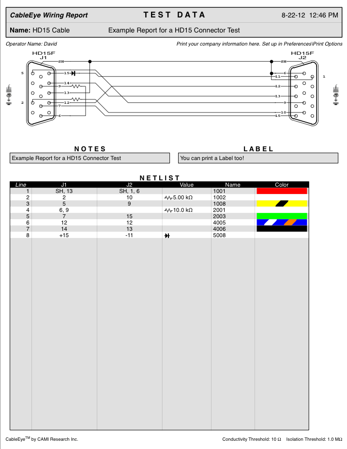
Click the "Print" button to produce hard copy documentation of your cables. Additional pages are printed for long wire lists or notes. Print a hard copy or to a .pdf file. You may also transmit this drawing directly from the CableEye software.
To download a sample report, click the following image. Click here for more examples of reports and labels.
Optional Software
Next Topic | Previous Topic | TOC
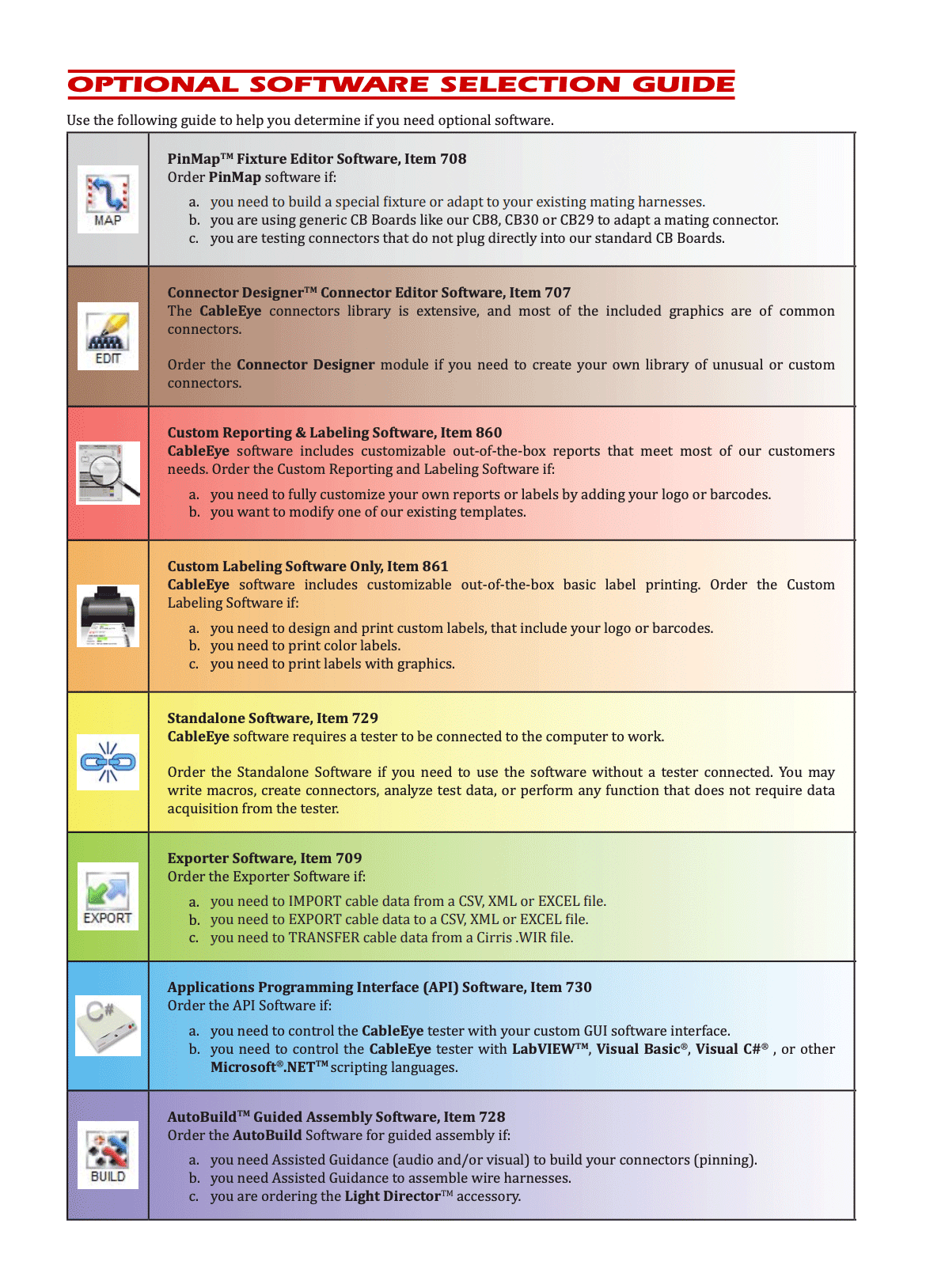
All features described above are part of the standard operating software that ships with all CableEye tester. Optional add-on software is also available for purchase that enables guided assembly; fixture mapping; connector graphic creation of unusual connectors; use of the software without the tester; an Applications Programming Interface and more. Keep scrolling for descriptions of some of these optional modules.
Guided Assembly | Test While Building
(An add-on option)
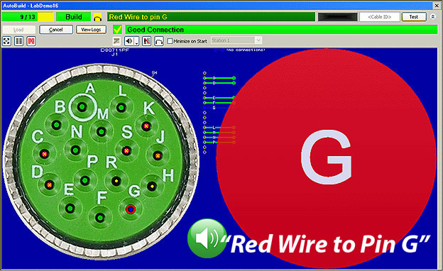
Next Topic | Previous Topic | TOCUse our AutoBuild™ software for guided assembly with speech for cable and wire harness manufacturing. During construction, the technician touches an unterminated wire using either a probe, or a finger with wriststrap, and the software reads the intended connection point using high-quality synthetic speech. The software also shows a connector graphic with the target pin highlighted. Once the connection is made, audible feedback confirms a proper connection or warns of an error.
Synthetic speech increases throughput, and helps the technician avoid repetitive motion injury to the neck and shoulders by eliminating the need to look constantly between the workpiece and the videoscreen. A simple half-open headset permits the speech to be easily heard in a noisy environment without interfering with other workers.
Use the voice fonts included with your Windows™ operating system, or purchase Item 792 voice fonts available in English, Spanish, German, and French.
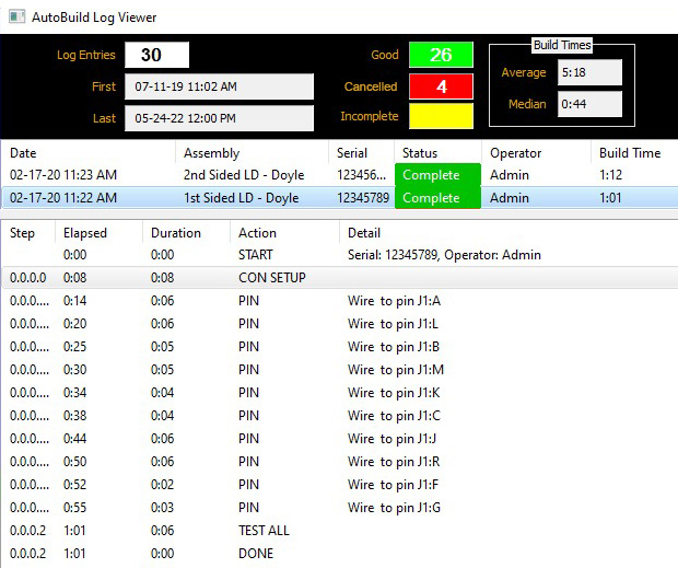
View build statistics and operator performance from the printable log. All insertion steps are logged, so that in the event of power failure or computer malfunction, the build can resume when normal operation is re-established.
Augment with CAMI's Light Director ™ guided-assembly accessory for even greater assembly speed and accuracy. With this, the target cavity is illuminated allowing for heads-down assembly.
Test as You Build
Using AutoBuild™ guided assembly software, the operator follows spoken and visual instructions for first-sided then second-sided pinning. When performing second-sided pinning, they will place the wire in the target cavity and test for continuity. A warning will be triggered if the wire is inserted into the wrong cavity. To initiate the instruction they can touch the screen or, while second-sided pinning, they may choose to use a probe. The system can also be readily programmed to advance to the next instruction on the pressing of a foot pedal and could be scripted to advance automatically when an inserted wire is a PASS for continuity.
Note: Not compatible with M2-Series Models.
Board-Mounted Configurations Available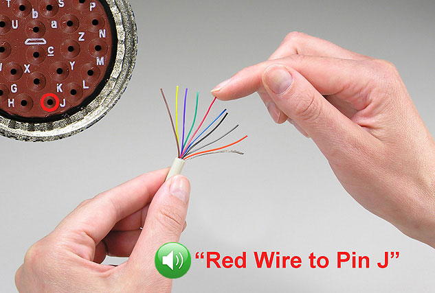
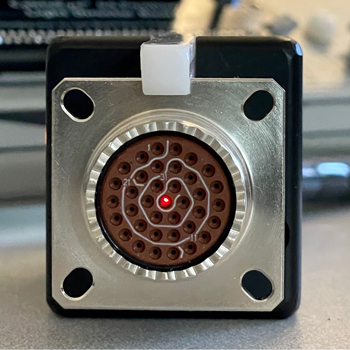
Handheld ZIF Light Director ™ Fixture
Fixture Mapping
(An add-on option)
Next Topic | Previous Topic | TOC
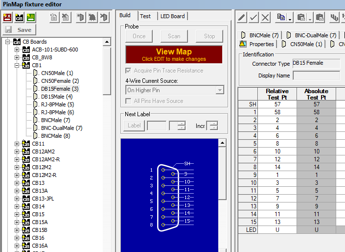
Check out this fast and super-easy pin-mapping process enabled by our PinMap™ fixture editor. Map as fast as you can move the probe from one pin to the next. Use on your custom connectors, test fixtures, specially-built connector panels, or pigtail adapters to your CableEye tester. This software assigns test point numbers to connector types and applies standard pin designations to the pin numbers.
Mapping a Fixture
PinMap software provides visibility of fixture maps including those of stock boards: The example given here of our stock CB1 board, shows the connection between every pin of the DB15 male connector (mating part for the DB15 female cable connector) and the 64-pin header on the front (relative to Bank 1 on the tester). This provides the same information as a wiring diagram or netlist would, but in a more convenient form.
Viewing Fixture Maps | Stock and Custom
Connector Editing
(An add-on option)
Next Topic | Previous Topic | TOC
The CableEye® Connector Designer ™ connector editor software lets you create custom graphic images for unusual connectors not found in our library.
This application aims primarily at the many and varied kinds of circular connectors found in military and aerospace applications and permits you to choose a graphic size, position, and pin numbers, as necessary. It is particularly helpful for very uniquely configured devices such as catheters. Click the button for further details and screenshots.
Connector Graphic Files Created with Connector Designer Software.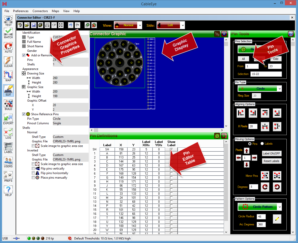
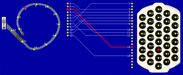
Test Result of Connectorized Catheter.
API
(An add-on option)
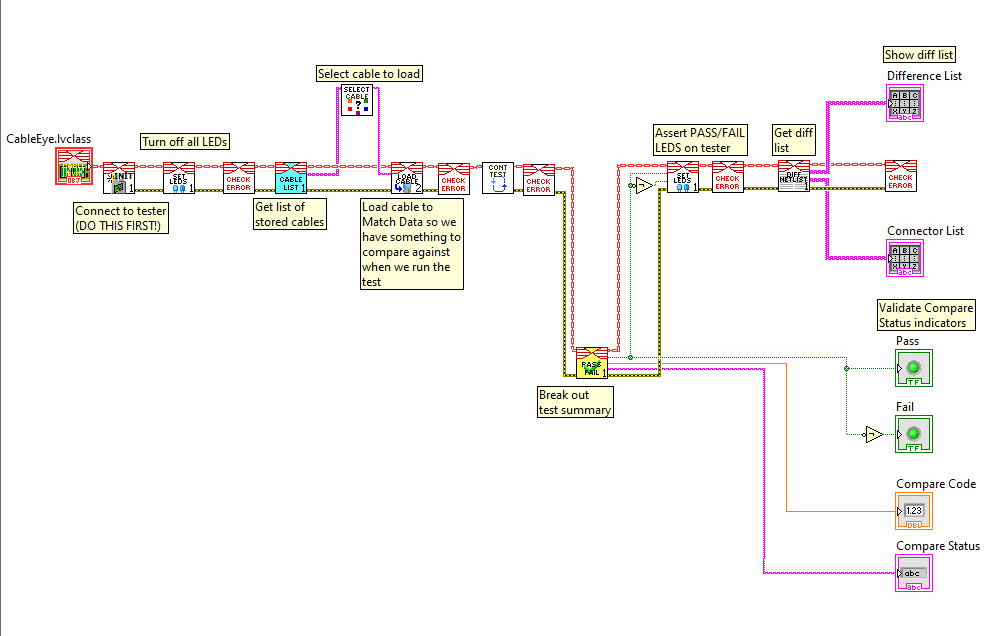
(Last Topic) | Previous Topic | TOCUse this software to link your tester to an external control program. A LabVIEW interface is included with which you can integrate tester control directly into your LabVIEW program.
The API provides a library of software primitives used to exercise control over all basic functions of the tester. This lets you embed the tester function within a larger system that may include control of cable lockdown, printers, diverter gates, pass/fail marking devices, and automatic modling equipeet.
If you need to create a custom GUI, you should order this option.
Quicklinks:
Software Introduction Guide
A step-by-step explanation of how CableEye software works.
CableEye Unique Benefits
An illustrated presentation of how a CableEye cable and harness test system can help you.
Product Selection Wizard
Select your optimal test system in just seconds.
Technical Specifications
Compare, contrast, and plan for future growth.
Videoclip Demonstrations
See how easy it is to design, test, assemble, data log, report, label, and automate.
Hands-on Demo
Borrow a demo unit and take it for a test drive.
Product Catalog (html)
Specifications and part numbers for every item.