Attached and Detached Expansion
Modules are Available,
Expand the Tester to over 2560 Test Points
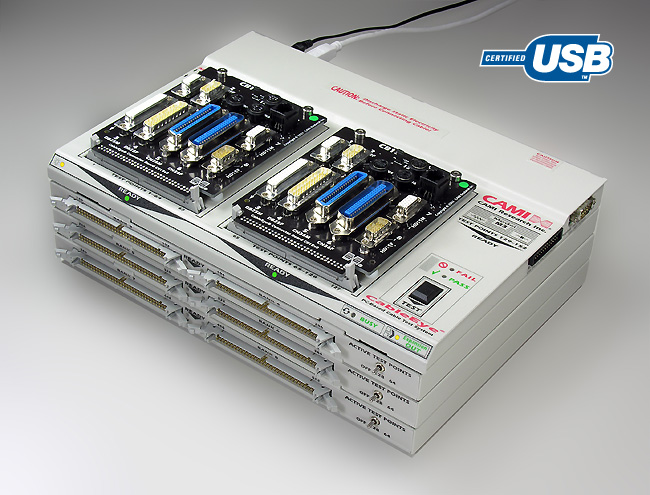
CableEye® with Three Attached Expansion Modules
The configuration shown here provides 512 test points for testing large cables, backplanes, or wiring harnesses. System includes a probe socket, remote control socket for use with a footswitch, external control panel, and external relay controls to synchronize tester with other equipment. Software API available for external control by customer Visual Basic or LabView programs. Relay board available for external control of solonoids, alert lamps, and bin diverters. Free demo systems available!
Expand CableEye for Wire Harness Testing
|
Screw-Terminal Transition Board
|
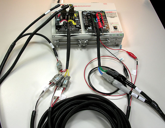
Harness Example 1: Testing a Small Harness
This harness has several long legs and is brought to the tester coiled on a wheeled cart. The test operator positions the cart in front of the tester and conveniently attaches the adapter cables to mating connectors labeled to agree with the numbering on the harness connectors.
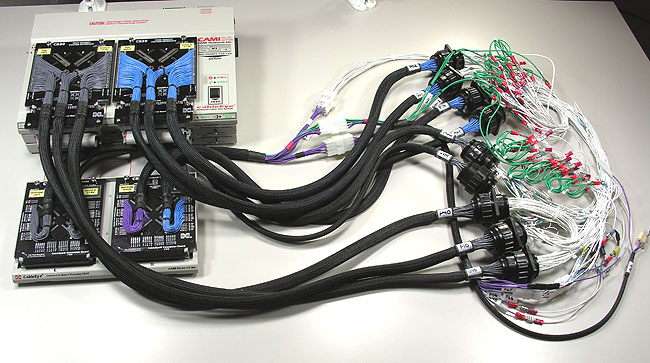
Harness Example 2: Testing a Large Harness using Adapter Cables
This complex harness (right side, white and green wires) was designed to fit behind the instrument panel of an aircraft. To test it, we built a series of adapter cables that link to the harness's closely-spaced circular connectors and series of ground lugs. The test operator places it on the test bench and connects the mating connectors. Clicking the Test button once produces a result in 2 seconds.
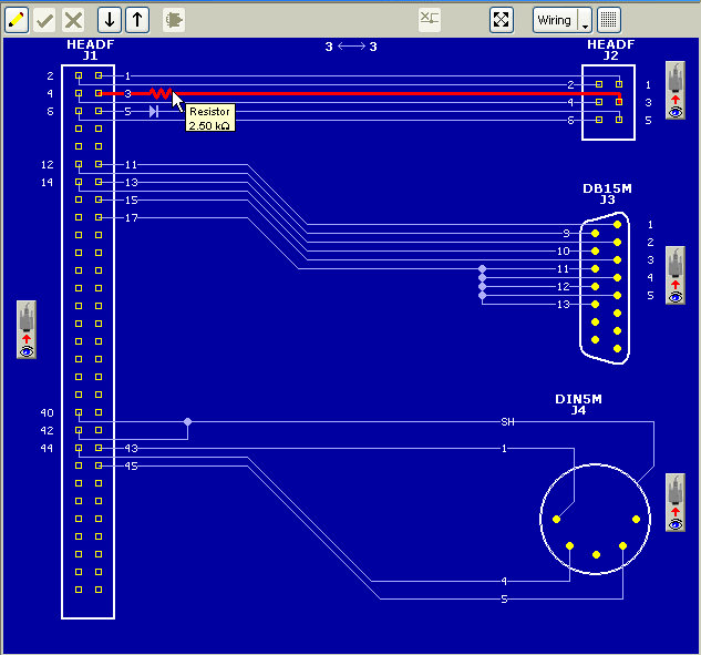
CableEye v5 Cable Harness Graphic Wiring Display
Graphically show the harness wiring with connectors and components. Screen buttons near each connector let you change the direction of view to orient the connector either into the pins or into the terminations. Connector images may be dragged to change position or side of the screen. Highlight wires or resistors for high-speed continuous testing to check for intermittent connections.
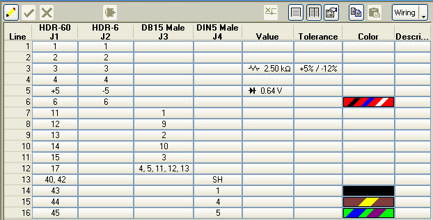
Advanced Netlist Display
The same data appearing in the graphic display above appears here in a more traditional netlist display. Show value, tolerance, and wire color, add a description, reorder connector columns as desired, resort pin numbers by any connector, and reformat multi-connector columns as a single to-from list if desired.