Quick Links
4-Wire Measurement
Next Topic | Previous Topic | TOC |
4-Wire Resistance Option
Added to the High Voltage Test System
Measures as Low As 1 Milliohm
A new option for the CableEye HVX high voltage cable tester that permits expanded testing for contact and wire resistance as low as 1 mΩ. After checking for opens, shorts, miswires, and resistance limits, the new 4-wire Kelvin measurement applies a user-selectable test current from 10 mA to 1 A to determine connection resistance within 1 mΩ. The resistance profile of a model cable may be stored and used as a basis of comparison during later testing to reveal cold solder joints, faulty crimps, recessed pins, pin contact contamination, improper wire gauge, and stress-extruded wire.
Four-wire measurement eliminates any effect of fixture resistance to obtain a precise value of the unit under test (UUT) resistance only. The same high-accuracy measurement may be obtained with a short fixture attached directly to the tester, or with a large wire harness fixture that may extend a considerable distance to reach the UUT. Users may optionally set up a high-current stress test for wiring by driving up to 1 A of current through each conductor, and setting a dwell time from 100ms to 3 minutes. Increasing resistance during the dwell period may show problems not detected with a shorter measurement interval.
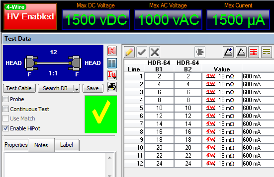
Screenshot of the CableEye Software.
The netlist table displays the measured 4 wire resistance in each conductor.
USB 3.0 Connector Board
Next Topic | Previous Topic | TOC |
Item 756, CB26 Small Frame Motherboard
Item 756N, CB26N USB 3.0 Connector Board
CB26N accepts USB 3.0 Types A, B, and Micro A/B connectors. The Micro A/B connector accepts both USB 2.0 Micro A and Micro B connectors. Requires the CB26 Small Frame Motherboard (Item 756) for operation. Set of two boards.
Photo shows CB26 (black) with the CB26N (green) plugged into the first slot. The second slot is available for another plugboard. See close-up of connectors below it.
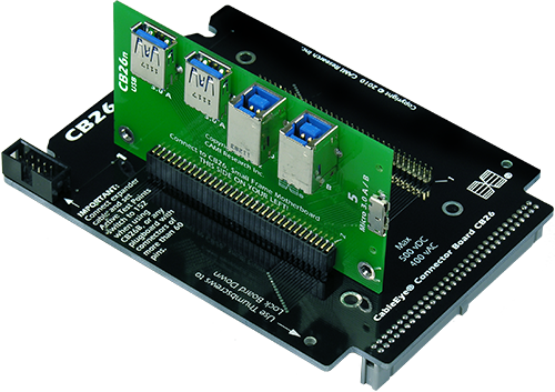
CB26 Small Frame Motherboard with CB26N USB 3.0 board mounted
CableEye® High Voltage Test System
Next Topic | Previous Topic | TOC |
Click for Complete Information . . .
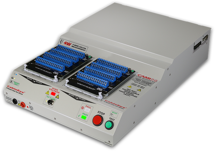
CableEye M3U Tester with
HVX High Voltage Expansion Module
and CB2 Board Set
Our new CableEye HVX Module adds 128 test points of high voltage capability to any M3U tester, providing 1500Vdc and 1000Vac, adjustable in 1V increments from 10V to the maximum voltage permitted. Ramp Up, Ramp Down, Dwell Time (same as Test Time), Trip Current, and Trip Delay (same as Soak Time) may be programmed for your specific requirements.
Existing customers may provide their present M3U tester for attachment to the HVX module, or order an HVX with a new M3U. Expansion modules which provide 128 points per module will be available by December. Quantity discounts are available. Initially, the system will be expandable to a maximum of 512 points.
Most existing CableEye connector boards may be used with the new equipment to test up to 1000Vdc. We plan to release a limited number of new CB boards for applications that require testing to voltages above 1000Vdc; contact us for availability.
The new system will operate as the M3U does now for low voltage testing, and then optionally perform a hipot test up to 1500Vdc or 1000Vac. Many safety protections have been built into the system, including a fast-trip 1.5mA current limit, manual high voltage enable function at startup, and login control by the system administrator to ensure that every User has been properly trained before their login name will enable the system for high voltage testing.
Universal power input of 100-240Vac, 60W maximum. Requires two USB channels, and Windows XP-SP3 or later. Compatible with touch screen and laptop PCs.
Weight: 13 lbs (5.9 kG), Size: 12.5" wide, 18.5" deep, 3" high.
Includes one-year warranty with one year free tech support and software upgrades.
Light Director™ System
Next Topic | Previous Topic | TOC
Click for Complete Information . . .
Our Light Director™ system (patented) provides a new, computer-guided technique for assembling connectors used in aerospace, medical, and other high-reliability applications. This system uses light fibers driven by super-bright LED lamps to individually illuminate target cavities in the connector being assembled. When the technician enters the wire code printed on unconnected wires, or touches a wire connected at the other end, the CableEye software turns on the appropriate fiber, thereby causing a bright, flashing light to project from inside the target cavity guiding the technician to the proper insertion point. Correct insertion is confirmed by the elimination of light from that location, whereas insertion into an incorrect location leaves the flashing light visible.
The Light Director also employs high-quality synthetic speech in English, Spanish, or French to read the pin number to the technician, further reinforcing the target location. Speech recognition is also available as an option permitting the technician to read wire codes to the system, thus eliminating the need for a keyboard or monitor.
Normally, technicians crimp pins on wires in advance of assembly to the connector. Wires may be identified during the assembly process by numeric code, bar code, color code, or if no codes are present, by electrical detection using a wrist-strap if the far end of the cable has already been assembled and can be electrically connected to the system.
Field testing has shown that the Light Director doubles assembly rate over manual methods while nearly eliminating errors. Because the Light Director greatly reduces the perceptual challenge of manually locating pin cavities in a complex connector, technician fatigue is greatly reduced, permitting a continuous, high productivity rate throughout the work day.
The Light Director™ system is an accessory for CAMI's CableEye® PC-Based cable test system. Customers purchase a mounting kit for each mating connector consisting of a CableEye plug-in board with special LED sockets, LED light fibers, fiber guide boards, a connector support board, and hardware kit. All parts are reusable. Requires the AutoBuild Guided Assembly Software (Item 728).
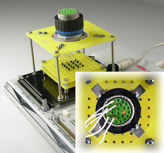
(shown with protective cover removed to reveal construction)
API Software Option
Next Topic | Previous Topic | TOC
Item 730, CableEye Applications Programming Interface (API) Software
CAMI Research’s CableEye® Cable and Wire Harness Tester normally ships with a complete software application for production, incoming inspection, and R&D. We now provide an optional "Application Programming Interface" (API), a software library that enables control of the tester by an external program. Test engineers may now write software for CableEye in Visual Basic, VB.NET, C++, C#, or from any software environment that can host our Active-X software interface.
The API provides a library of software primitives used to exercise control over all basic functions of the tester. This permits engineers to embed the tester's function within a larger system that may include electrical cable lockdown, label printing equipment, pass-fail marking devices, diverter gates, and automatic molding equipment. Engineers may even write their own fully-custom user interface for the tester for special, simplified applications like a touch-screen display.
The CableEye tester checks cables and wire harnesses for opens, shorts, and miswires, measures diode forward voltage, checks resistance values over the range of 0.3 Ω to 10 MΩ, and tests conduction and isolation resistance against specified thresholds. The API option adds $495 to the system price for a site license. Available from stock. Demo systems available for no-charge evaluation.
Visual Basic Editing Screen with Form and Code Example
Multilingual Text Option - Japanese
Next Topic | Previous Topic | TOC
Item 726, CableEye v5 Software Upgrade
![]()
CAMI Research Inc. (Acton, MA) has added a Japanese language option to its standard CableEye cable and harness testing system Graphical User Interface (GUI). The intuitive, graphic-rich GUI provides a clear simple operator interface for production workers, and may now be user-set to any of seven global languages: ENG, ESP, DEU, FRA, TUR, CHN, JPN.
Comprehensive Translation
A leader in development of PC-based Cable & Harness Test Systems for over 20 years, CAMI offers the CableEye suite of Low and High Voltage products complete with accessories. Users interact with any of its models through an identical GUI, as the systems are united by a common platform.
Translated by native speakers to ensure clarity, all seven language options are provided in CableEye’s standard software as well as its PinMap™, Connector Designer™, Autobuild™, and Exporter software options.
The language setting affects anything presented on the screen (including associated print options), such as its ‘standard’ comprehensive reports, color-coded net lists, scripting, and user-defined/annotated cable database entries.
Exacting Reporting Standards
CableEye software allows customers to meet the most exacting reporting requirements of governmentcontracted and ISO 9000-style certified companies … in seven languages.
Price & Availability
All seven multilingual GUI settings come with the standard software shipped with any new CableEye test system. Users of older systems may update their software to version 5-B1187 or later to acquire Japanese functionality. Upgrades from Version 4 or earlier software may be purchased for $295 (Item 726), or downloaded for free from our Customer Support site with a valid Warranty. Warranty renewals start at $160 for an M3U system without expansion modules and includes CableEye’s standard one year Warranty which is combined with free tech support and free software upgrades.
| English | Spanish | |
|---|---|---|
 |
 |
|
| French | Turkish | |
 |
 |