Computer-Guided Harness Assembly


10 pages, 2.1 MB

Table of Contents
1 Background
2 Historical Approaches
3 Assembling Connectors
4 Computer-Guided Assembly
5 Assembly Methods
6 Cost-Benefit Analysis
7 Alternative Technologies
8 Summary and Conclusions


Next | Previous | TOC

1 Background

Advances in computer automation over the last 30 years have brought huge increases in productivity to electronics manufacturing. Populating printed circuit boards with components, soldering, cleaning, inspection, and test can now be handled almost entirely by computer-controlled machinery. Not only have the costs of computing engines dropped radically, but software advances in machine vision, gauging, sensors, control, and testing have brought us manufacturing facilities that can operate tirelessly, and err only to the extent that flaws in their programming remain undetected.

Unfortunately, cable and wire harness assembly have not seen such marked advances. The core task of inserting pinned wires into connector cavities relies largely on the acuity of human vision to guide marvelously dextrous human fingers, a feat of computation and control that cannot be equalled by any present-day machine. Nonetheless, we seek methods within reach of current technology that provide helper functions for assembly technicians whose job it is to mate pinned wires with connector shells, the most time-consuming and error-prone aspect of harness assembly.

In general, we have three aims:

1 - Reduce the abstraction level of pin location.

2 - Minimize the physical motion necessary to insert a pin.

3 - Provide feedback to confirm that the insertion task is complete.

As we approach these goals, we will increase assembly speed, reduce the error rate, and, perhaps most importantly, reduce the fatigue experienced by workers performing this assembly task; lower fatigue levels enable technicians to function for longer periods without a loss of speed or accuracy.


Next | Previous | TOC

2 Historical Approaches

Cable and harness assembly represent only one instance of an electrical and mechanical assembly task that has not quickly yielded to automation. For such tasks, computers are used to display sequential images of assembly steps, project light onto an assembly panel to direct the technician’s attention to the next operation, provide spoken instructions, and respond to spoken words. Bar code scanners eliminate the manual reading of numbers on components or wires, vision sensors detect color, and image processing enlarges or enhances a video image to enable reliable judgment by the human eye. These technician aids have advanced the state of the art by eliminating, one-by-one, complex processes that computers and machines are increasingly able to perform.


Next | Previous | TOC

3 Assembling Connectors

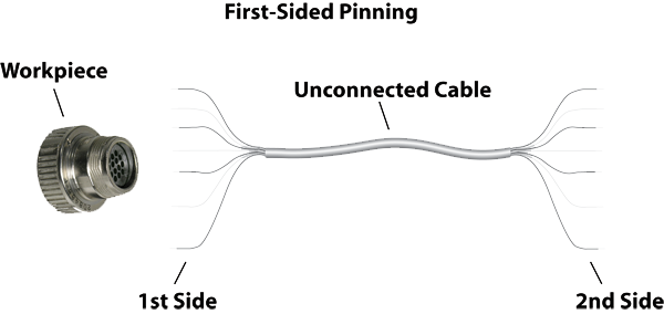
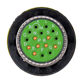
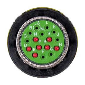
Connectors commonly used in wire harnesses involve an open connector body with separate pins. The technician’s chief job is to insert pinned wires into the appropriate cavities in the connector body according to a printed build list. The perceptual challenge involved in this highly repetitive task invites error and fatigue. These are the issues:

1 - Pinned wires must be identified.

A numeric wire code, color code, or insulation color normally serves this purpose. While advanced scanners may be employed, it is not common because of the expense involved. Most applications rely on the technician’s vision. When numbers identify wires, reading these numbers printed on a curved surface and remembering them, especially when many digits are involved, taxes both vision and memory.

2 - The wire ID or color must be looked up in build list, and remembered, to find the target cavity.

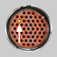
3 - A labeled rubber grommet or formed plastic shell on the connector body must be searched to locate the target cavity.

For connectors with few pins or large openings, each cavity can be numbered clearly. Unfortunately, this often is not true. Instead, a number may be equally near to two cavities leading to potential confusion. In some cases, the pins are so numerous or so dense as to make numbering for each cavity impossible, and the technician must count forward or backward from reference points.

4 - The pinned wire is inserted into the target cavity.

Manual methods do not normally provide feedback at this point to confirm that the wire has indeed been inserted into the correct cavity.

To perform this task accurately, efficiently, and repeatably over the course of a work day, the assembly technician must be skilled, well-trained, and able to manage common distractions in the workplace. Even a skilled worker becomes fatigued in these tasks as the work day progresses, leading to slower performance and increased likelihood of error.


Next | Previous | TOC

4 Computer-Guided Assembly

In late 2008, CAMI Research introduced a computer-aided assembly system to simplify the tasks identified above. The Light Director™ system uses light fibers driven by super-bright LED lamps to individually illuminate target cavities in the connector being assembled, as shown in Figure 1. When the technician enters the wire code printed on unconnected wires, or touches a wire connected at the other end to a sensor, software turns on the appropriate fiber, thereby causing a bright, flashing light to project from inside the target cavity guiding the technician to the proper insertion point. Correct insertion is confirmed by the elimination of light from that location, whereas insertion into an incorrect cavity leaves the flashing light visible. See a videoclip demonstration at


55-Pin Souriau.jpg

Figure 1 - An illuminated target cavity.


Figure 2 shows how light follows the fiber into the connector cavity, while Figure 3 shows a mounted connector fixture. The connector fixture is shown mounted on the test platform and ready to use in Figure 4.

In addition to an illuminated target cavity, the system provides spoken instructions to reinforce identification of the target, and a graphic image of the connector with the target pin highlighted to permit easy recovery from interruptions. Insertion into the correct cavity is confirmed when the flashing light disappears. Speech recognition may also be employed to allow the operator to issue commands, like “Next”, or read color codes or numbers.

This automated guidance greatly reduces operator fatigue, assembly time, and error rate by eliminating the need to manually locate pin positions. Field experience with the Light Director guided assembly technology has shown productivity improvements of 20-50% while at the same time reducing the error rate to near zero.


Figure 2 - Light fiber driven by a super-bright LED lamp.


Figure 3 - Connector fixture with shroud.

Figure 4 - Connector fixture mounted on a test platform ready to begin assembly.


Next | Previous | TOC

5 Assembly Methods

Wire harnesses vary widely in the number of connectors, number of wires, pin count, length, and other factors. In simple cases, wires extend one-to-one between two connectors. In other cases, large, complex harness boards support dozens of connectors and may include flying leads, mechanical interlocks, rubber boots, and complex hoods. The assembly process may, in general, be divided into these functions:


1 - First-Sided Pinning

In this situation, the pinned wires ready for insertion into the connector body have no electrical contact with the system. Wires are identified solely by codes printed on each wire or by the wire’s insulation color. The wire code alone must be used to determine the target cavity. First-sided pinning always applies to the first connector assembled in a harness and may, if desired, be applied to all connectors. Figure 5 shows the setup for first-sided pinning.

The design and printing of wire codes on the insulation largely determines the suitability of first-sided pinning for automation. In order of speed, one of these methods may be employed:

1 - Wire Scanner – A scanner capable of reading bar code, color code, or text printed on the curved surface of the insulation would be the fastest and most accurate input scheme for wire codes. Either a handheld scanner brought near printed code, or a fixed scanner with a slot through which the wire is pulled, might be used. The handheld scanner has a limited field of view and may not work for long codes. Scanners of this type represent emerging technology and generally are not ready for widespread use.

2 - Speech Recognition – Software available for most computers may be used for direct speech input. This is known to work well for English speech recognition using the Windows VP-SP3 or later operating systems, and is suitable for reading wire color or short (3-4 digit) numeric codes. When dictating wire codes, the highest accuracy results when a checksum digit is added to the wire ID allowing the computer to immediately flag misread data.

3 - Mouse Input. We rely on the operator’s eyes to read the numeric or color code in this case, and click on a matching color bar or number displayed on the computer screen.

4 - Keypad Input. When none of the previous options is suitable, wire codes may be typed in manually using a numeric keypad. When the code consists of more than three or four digits, or if check digits cannot be used, this method becomes impractical and may actually slow down the overall assembly process.


2 - Second-Sided Pinning

When pinned wires ready for insertion have previously-attached connectors at the far ends, electrical fixtures which mate to these connectors may drive signals into the wires. This permits an electrical probe, or finger with wrist strap, to identify wires by touch, eliminating the need to input wire codes into the system. As a result, we realize a huge speed and accuracy advantage because electrical sensing makes unnecessary all of the complexity associated with entering wire codes.


Electrical sensing of unattached wires has other advantages. Once detected, the system speaks both the color (or code) of the wire and the target cavity. If you touch a red wire and the system says “Blue Wire to Pin A”, you have identified a miswire on the first side. Refer to Figure 7.


3 - Seal Plug Insertion

Unused cavities often require seal plugs before the connector is closed. The Light Director assembly system guides the assembly technician in this task also. By flashing all unpopulated cavities simultaneously, the technician adds plugs until all light ceases. Typically, this step occurs before pin insertion.

Figure 8a - Unused cavities flashing.

Figure 8b - Seal Plugs Inserted.


4 - Testing the Finished Assembly

The test platform controlling the Light Director accessory and sensing unattached wires for second-sided pinning may also perform an electrical test on the completed assembly. This becomes practical when the harness does not span a great distance on the harness board and offers two advantages. First, the test can be performed without removing the workpiece from the harness board or detaching it from the system. Second, the operator will find errors immediately before closing the connectors or removing them from the fixture.


Next | Previous | TOC

6 Cost-Benefit Analysis

An initial one-time investment in the test platform and software, and ongoing investment in new Light Director assembly fixtures and electrical interfaces, must increase productivity sufficiently to warrant the expense. If we find a saving in labor cost on each cable, and an overall reduction in rework due to improved accuracy, cost savings increase directly with the number of cables assembled. We need only to find the crossover point where the total saved labor and rework expense surpass the cost of the fixturing.

Example: Assembling and testing a 64-wire two-ended cable.

A 256-point test platform consisting of CAMI’s CableEye® tester, AutoBuild™ software, and high-quality voice font requires a one-time investment of about $3400, with a five-year depreciation lifetime. This 256-point system has sufficient capacity to mount two 64-pin Light Director boards and two 64-pin electrical interfaces to provide for first-sided pinning, second-sided pinning, and electrical test. Including yearly calibration and extended warranty, the capital cost is approximately $75 per month per station.

For each connector, allow approximately $450 per Light Director™ board for the board kit, LED fibers, mating connector, assembly time, and programming. Because the electrical interface will be required to test the completed assembly whether it is assembled manually or with the Light Director guided assembly system, the cost of the electrical interface applies equally to both methods and need not be considered in judging payback on the Light Director accessory.

Assumptions:

The 64-pin two-ended cable requires 2 hours to build manually.
The loaded labor cost is $20/hr.
Four cables per 8-hour day are assembled.

1 - Cost Savings per Day

Labor Cost for Manual Assembly: 8 hrs x $20/hr = $160

Labor Cost for Light Director Assembly

Light Director at 40% faster assembly: 4.8 hrs x $20/hr = $96

Light Director at 25% faster assembly: 6.0 hrs x $20/hr = $120

Savings in labor cost per day (40%): $64

Savings in labor cost per day (25%): $40

2 - Fixture Payback Measured in Work Days

At a cost of $900 for two fixtures, the payback time is about 14 days if you are saving 40% on assembly labor, or 23 days if you are saving 25% on labor.

3 - Fixture Payback Measured by Number of Cables Built

Manual Assembly, 2 hrs per cable x $20/hr = $40

Light Director at 40% faster assembly: 1.2 hrs per cable x $20/hr = $24

Savings per cable: $16

Light Director at 25% faster assembly: 1.5 hrs per cable x $20/hr = $30

Savings per cable: $10

At a cost of $900 for two fixtures, the number of cables built to payback fixture cost is 56 cables if you are saving 40% on assembly labor, or 90 cables if you are saving 25% on labor.

4 - Other Factors that will Reduce Assembly Cost when using the Light Director

• Because of increased accuracy, rework cost will be lower.

• As a result of a lower fatigue level, worker output will be higher overall.

• The Light Director guided assembly components may be reused for new projects, reducing future fixture expense by at least 25%.

• By using an actual mating connector during building, you assure proper fit of the build connector and keying slots.

• By immediately following the build process with test, any errors found may be corrected at the build bench without remounting the cable. Hipot testing may be integrated with the Light Director system if desired.


Next | Previous | TOC

7 Alternative Technologies

The Light Director guided assembly system identifies target cavities by projecting light into the cavity from below. Other technologies introduced over the last few years offer guided assembly by, in one case, projecting light onto a target cavity from above, and in another case by imaging the connector from above and superimposing a graphic that identifies the target. Each method has advantages which depend on the application and number of connectors to be assembled. Overhead projection or imaging systems require no mating connector or fixture, but both of these methods prevent close-in viewing of the workpiece, and one requires the unnatural task of looking at a monitor in one direction while your hands work in another. Further, these systems are applicable to first-sided pinning only and cannot offer the speed benefit of second-sided pinning, or integrated test. For assembly volumes above 75 to 100 units, fixturing costs associated with the Light Director guided assembly system are quickly repaid, and the ability to combine first- and second-sided pinning with electrical test offer speed and worker endurance advantages unequalled by competing technologies.


(end) | Previous | TOC

8 Summary and Conclusion

The assembly of cables and harnesses using high-reliability connectors suitable for aerospace, military, and certain industrial applications depends largely on human technicians because of their exquisite vision and finger dexterity. While machine vision and robotics continually advance, present-day technology cannot provide cost-effective automation to replace the assembly technician. However, automation increasingly provides helper functions that reduce the perceptual challenge associated with manual assembly, resulting in increased assembly speed and lower error rates while reducing worker fatigue level associated with manual methods. Because of the large increase in productivity offered by such systems, assembly shops failing to apply this technology risk being underbid on new jobs by companies that do.