Zero Insertion Force (ZIF) Light Director Fixture
Our default Light Director assembly fixture uses a ZIF fixture subassembly, also referred to as a Light Director head or block. In addition to presenting an even brighter light to the assembler, it provides easier and more rapid connection and disconnection of the connector being assembled achieving even greater productivity.
This type of fixture is available when connector pin-to-pin centers are spaced by 1.5 mm or greater. You will need to send a sample of the build connector if you order this type of fixture.
Examples of ZIF style fixtures are shown in the previous tab labelled "ZIF/LIF".
Original Light Director Fixture
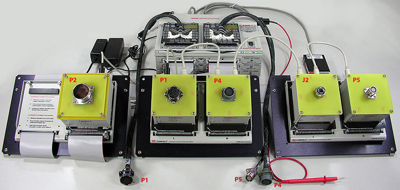
Our original Light Director fixturing uses an actual mating connector. The method requires attachment of the build connector to the mating connector on the fixture whether by screwing or pushing one onto the other.
We recommend this approach when pin-to-pin centers are spaced by less than 1.5 mm. You will need to supply the mating connector and a sample build connector if you order this type of fixture.
Examples of original style fixtures are shown in this tab.
See how these original Light Director fixtures are customized for diverse test applications — examples and photos below.
+1 978 266 2655
Explore Additional Industry Applications
CableEye® technology is used across a wide range of industries and testing scenarios beyond those represented within the tabs of this page. Explore additional application examples showing how industry applies CableEye test systems to different cable types, test requirements, and production environments.
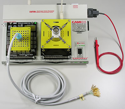
1 - The cable shown here has a connector on the left side attached to an electrical interface we built for it, and bare pins on the right side. These pins are to be inserted into a build connector mounted on the Light Director™ board you see on the right.
Once the AutoBuild™ Guided Assembly Software (catalog Item 728) is started, the operator touches the red probe to a loose pin, and the target cavity begins flashing in the build connector. The operator then inserts the pin with a special tool, and presses the black button on the tester to advance to confirm insertion.
Note that the pins in the medical cable are so small that they must be handled with a tweezers and inserted while viewing the build connector through a magnifying scope.
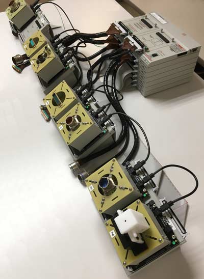
3 - This 896 test point system with four QuickMount housings on tilt stands, is configured for 1st- and 2nd-sided pinning using Light Director guided assembly..
The Light Director assemblies, consisting of both original and ZIF fixture styles (refer to ZIF/LIF tab), are attached to the QuickMount housings.
The flying leads are the electrical fixtures required (in combination with the Light Director fixtures) for 2nd-side pinning.