Cable and Harness Manufacturing:
Productivity through Flexibility
CAMI Research Inc.

Choosing a flexible wire cable and harness test system is part of a decision process that supports improved productivity. A truly flexible system will ensure usability, and thus investment longevity, across product lines, lifecycles, and generations. As a consequence, such a system must handle extensive product complexity, and have a comprehensive test portfolio. In so doing, it will remain relevant as product design changes. Naturally, the system must also provide fast, reliable, and accurate tests.
System Flexibility
A flexible system (Fig. 1) provides value to a broad range of users: It will address job function and language differences, supporting a seamless workflow from Design through Shipping. To help achieve this, the system must offer customizable workstations. touch screen compliance, and a multilingual Graphical User Interface (GUI). In so doing, the user sees only the features required for their job function - whether full Engineering and QC design and test diagnostic capabilities, or simple pass/fail automated testing on an operator's no-frills, touch screen production floor workstation. We note that any system that offers a GUI is necessarily PC-based.

Fig. 1: Cable and harness test system flexibility
Seamless Workflow
By way of example, consider a workflow scenario for a new product, consisting of a mission-critical cable with a complex connector, destined for volume production (Fig. 2). To demonstrate how we can benefit from a flexible wire cable and harness test system, let us assume the product traverses a design-to-ship workflow that passes through prototype and pilot manufacturing stages, before being ramped to volume in assembly and production.

Fig. 2: Integrated workflow - complex connector example
An engineer uses the design features to define the color-coded wiring schematic and netlist for the new product (Fig. 3). S/he defines connector type, resistance per wire, pin-to-pin connections, and wire colors, and even the test data against which the prototype will be measured. The annotated design saves to the database for quick, error-free pick up at the next stage of the workflow – in this case prototyping.
At the prototype stage, engineers build the First Article (‘master’) cable (or harness) against the saved design and prepare the test interface for proofing the ‘master’. This might involve simply selecting the appropriate plug-in test board if standard connectors are employed, or building a custom mating harness if the connector-types are unique.

Fig. 3: Netlist and wiring schematic
In this scenario, the Pilot Line takes over, developing assembly and manufacturing processes then test-driving a small production run to generate and verify a robust and manufacturable design. Since the product has a complex, mission-critical connector, the Pilot Line team wisely chooses to design-in light-guided assembly (Fig. 4) into the process. This will ensure fast production of high quality product (CAMI Research reports that its Light-Guided Assembly System can as much as double assembly rates over manual methods while nearly eliminating errors (Fig. 4)). The Pilot Line team prepares a custom-mounting fixture using a light-guided assembly kit, and sets up the GUI on a touch screen to help streamline the main assembly line workstations.

Fig. 4: Light-Guided Assembly Example, Kit, Time Study, and GUI.
GUI visual aids include a flashing red ring showing where to connect, a big colored balloon showing the name and color of cable to be inserted, and a color coded table showing progress of the assembly session.
Using the full suite of diagnostic tests (Fig. 5), the Pilot Line team proceeds to check the quality and reliability of the planned manufacturing processes. The test suite includes continuity, resistance, dielectric breakdown, insulation resistance, miswire, and intermittent defects. A truly flexible cable and harness test system will not be limited by connector type (or indeed whether a connector occurs at all), and will cope with long cables or no cables (e.g. backplane, PCB).

Fig. 5: Comprehensive Testing
With success on the Pilot Line, Assembly and Production prepare for higher volume production. Engineers roll out light-guided assembly systems on Assembler workstations, define test automation scripts, and customize each GUI. Customization includes setting the language and level of simplicity of GUI required for each test operator, and loading the test automation shortcut onto each operator’s touch screen test workstation. Being mission critical, the products need effortless traceability: the engineers include a call to print bar-coded labels when testing is passed – linking the product back to the schematics and data amassed in the test system’s database.
With flexibility comes versatility: The inherent breadth of completeness that comes with a flexible system, allows engineers to tap into a truly comprehensive list of test options (Fig. 5) to customize automation scripts, and prepare a wide range of Pass/Fail tests for the production floor. Products that fail the scripted tests may be passed to other workstations (e.g. QC) for more complete, unscripted, diagnostics. This illustrates just one way in which a manufacturer may adapt a versatile system to the needs of the facility.
Our workflow scenario concludes at Shipping, where the worker crosschecks the barcoded product against the order, and prints impressive traceable documentation for the customer - including a batch test summary.
This seamless workflow only exists because of a test system with an adaptable, expandable, modular design, underpinned by a PC. Modern PC-Based systems have the advantage of being able to capitalize on full-screen high-resolution color graphics, high-speed computation, large storage capacity, full-sized keyboard, mouse, trackball, touch screen, voice control, and more, while being compact and unobtrusive on the test bench.
Productivity
We can see that a test system this flexible encourages productivity at each workstation and across the workflow. At the workstation level, it can be as complex as required for design and diagnostics, or as simple as required for automated pass/fail testing. Yet, significantly, there remains a common look and feel at each workstation level, allowing staff to become productive quickly as they switch between product lines, products, or between job function levels. Moreover, as the product line changes and grows, the system can adapt in concert. Different types of test systems are not required at each stage of the workflow, resulting in minimal cross training. Even when switching, for example, from a low voltage product line to a HiPot product line, operators need little retraining, as the flexible test system HiPot hardware and software have a very similar look and feel. Empowered by a common system (across workflow and product lines), managers and supervisors enjoy being able to reassign operators with ease and confidence when faced with day-to-day staffing issues such as unexpected absences.
Our customers report amazing increases in productivity using CableEye test systems.
Christopher Strangio
CAMI Research Inc.
Maximum investment longevity (an important consideration when purchasing equipment) comes with a Cable and Harness Test system that not only has expandable and upgradable capabilities, but also remains backwards compatible for all system hardware and software upgrades. Such backwards compatibility will provide confidence that the capital equipment, test fixtures, data-acquisition electronics, connector cards, and the procedures and processes into which the system becomes embedded, remain viable.
The level of flexibility discussed here and above exists with PC-based cable and harness test systems such as the CableEye® system from CAMI Research. A PC-based system not only tests cables, but also provides an integrated software package for cable design, labeling, documentation, cataloging, data logging, on-line assembly checking, and test scripting. It supports elimination of errors in transcription, drawing, and rekeying of wire lists as cables pass through design, test, and documentation phases. The President of CAMI Research, notes, “Our customers report amazing increases in productivity using CableEye test systems. They have measured production time reduction in just the first few hours of use.” He adds that, “Significantly, for PC-based systems, new software advances can be applied to years-old hardware to keep pace with new test automation and reporting requirements. In fact, several of our customers are still using 15 year old CableEye systems because they have been able to keep them relevant by installing software updates.”
Summary
PC-based cable and harness test systems provide the flexibility that supports improved productivity. They ensure usability, and thus investment longevity, across product lines, lifecycles, and generations, and will remain relevant as product design changes.
To learn more about the software that drives the tester referenced in this artcle, click the button below.
CableEye ® Automation-Ready Cable and Wire Harness Test Systems
CableEye testers are highly versatile, expandable and upgradable diagnostic and Pass/Fail check Cable and Harness Test Systems that are PC-based. They are used for assembly, prototyping, production, and QC of standard or custom wire cables and harnesses The entire suite of products is powered by the same easy-to-use operating software and, with the help of its signature easy-to-interpret color-coded graphics, instantly identifies not only when there is a fault, but what type of fault and where.
Low Voltage M2 Series
For diagnostic and Pass/Fail Testing - Find, display, log, & document continuity (opens, shorts, miswires, intermittent connections).
Low Voltage M3 Series
For all of the above plus resistance (contact, isolation, embedded), and diodes (orientation, forward voltage, reverse breakdown).
Low Voltage M4 Series
For all of the above plus precision resistance (4-wire), and capacitance (twist wire relationship, length of cable, length to break, capacitors).
Low Voltage and High Voltage HVX Series
For all as described for M3 plus HiPot (dielectric withstand voltage and insulation resistance). 4-Wire Kelvin Measurement and Advanced Measurement Options (capacitance, twist wire relationship, length of cable, length to break, capacitors) are available.
Try One!
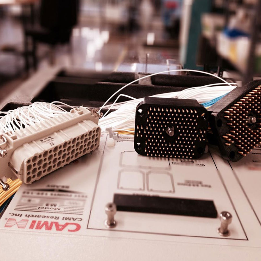
photo credit: Progressive Image
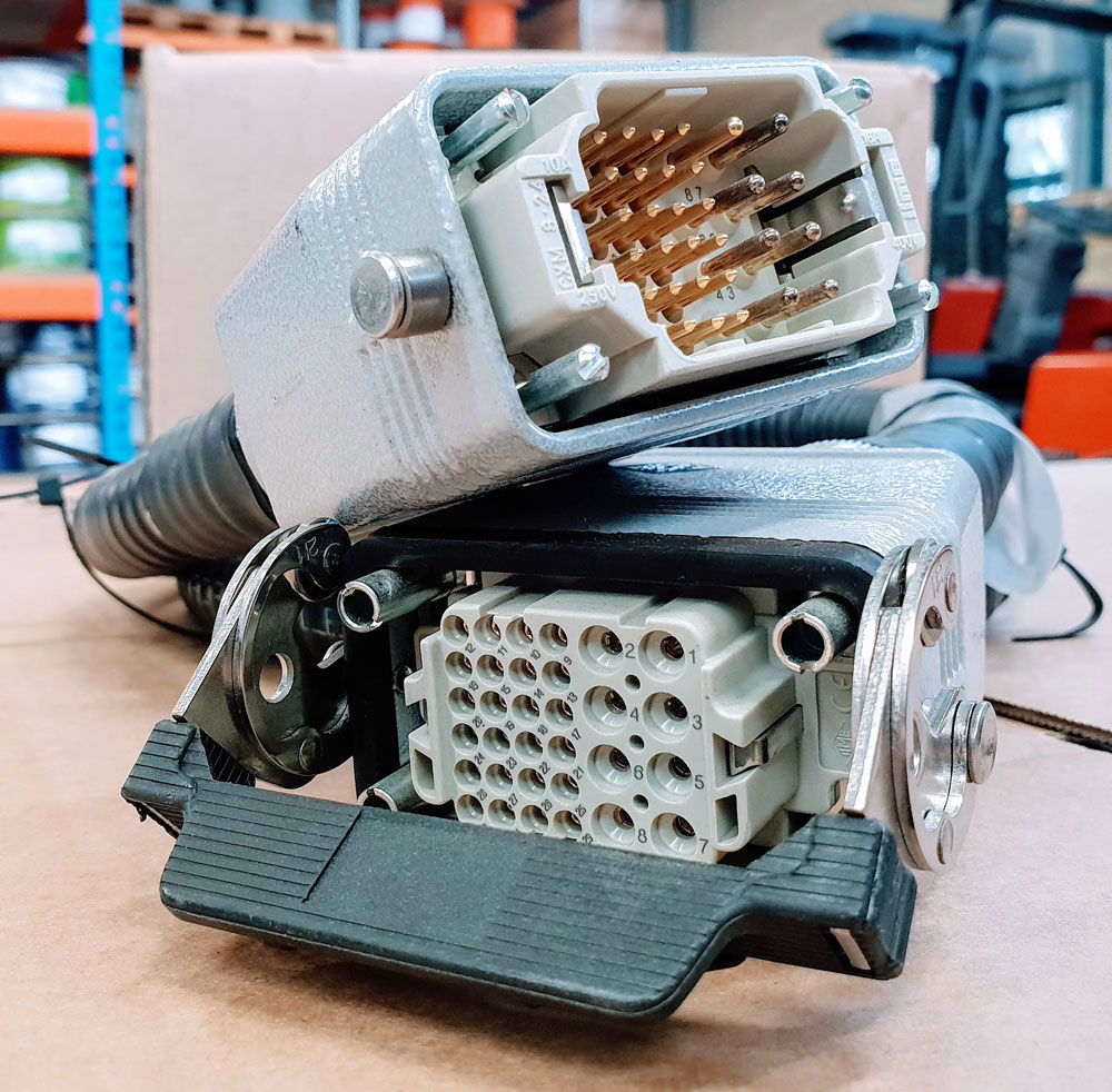
photo credit: AP Technology
"Our production guys find it simple to setup and use. Our clients love it as it provides complete traceability for each and every cable assembly we manufacture."
AP Technology, UK