Cable and Harness Manufacturing:
Cables in Motion - Diagnostics
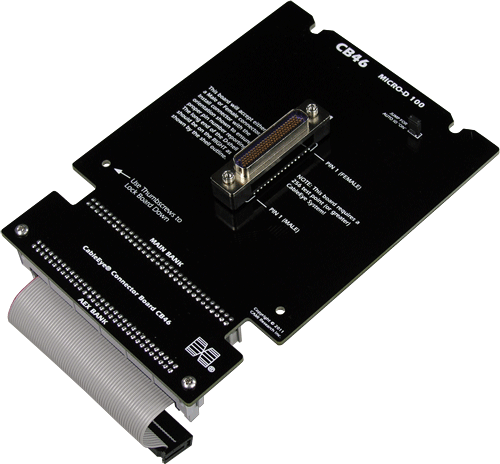
CableEye® CB46 Tester Adapter Board for testing cable with Micro-D 100 connector
Overview
Cables in motion experience fatigue causing complete or intermittent failures whether or not that motion is constant. Fortunately, there are cable and harness test systems that can easily identify and pinpoint the source of even the most elusive intermittent failure.
Flexibility
Cables may flex intentionally as part of a pre-programmed robotic move, or unintentionally due to operationally- or environmentally-induced vibration.
The most flexible test systems are backed by a large library of test boards that, for robotics applications, includes compatibility with, for example, nano- and micro-D connectors. For optimal flexibility and usability, these boards are mounted with ‘families’ of connectors or connector slots (Fig. 1). This is an especially agile and economical methodology, much appreciated by contract manufacturers and other companies where fast reconfigurability is necessary.
Such flexible Cable & Harness test systems may be used for all robotic applications, whether industrial, or service (e.g. personal, military, medical, logistic).
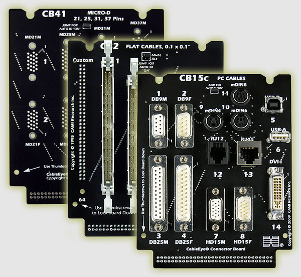
Fig. 1: Unlimited by connector type, connector adapter boards may be populated with groups of connectors, or left bare for customization. Shown above are examples of configuration solutions for USB, D-Sub, nano-D, micro-D, IDC Wire-Mount Sockets, and more.
Pre-Installation
Faults such as bad crimps, broken wires, and cold solder joints will result in intermittent connections. The issue is whether test equipment is sufficiently sensitive to detect them, and whether the test is applied at the earliest possible point in the value-added stream - the earlier the testing, the less the impact of any detected error.
Those who buy connectorized cables for robotic applications will want to ensure their suppliers are shipping cables that have passed intermittence testing under fast cycle times. In this context, a full cycle comprises a complete sweep through all test points.
Testing for Intermittent Faults
The intermittence test is properly performed when the sample rate is high enough to statistically capture enough random events to raise the confidence level in the test result to an acceptably high degree. Companies running stringent quality programs (such as Six Sigma) will be looking for the fastest cycle time possible. They need testers that deliver diagnostic information above a simple pass/fail, so they can provide quantitative and qualitative data to their process-improvement feedback loop.
Note that although the intermittence test mode is often referred to as the ‘continuous test’, the test signal itself is always pulsed in order to sweep through the full set of test points. In this context, ‘continuous’ simply means that the test is continuously sweeping through these test points.
Testers are available that will sample 128 Test Points with 100ms/cycle time using tester default settings, and as fast as 11ms/cycle by reducing both Dwell Time (to zero) and the number of test points. Even faster speeds can be achieved by adjusting other parameters. These same testers include a dynamic GUI for identifying the type and location of the intermittent error (Fig. 2), and can output ISO 9000-quality printed reports that include the same graphics.
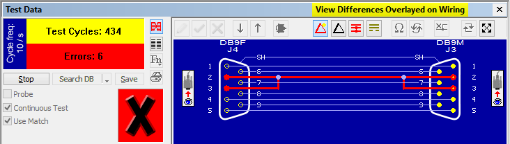
Fig. 2: Real-time intermittence testing identifies a) the number of passes and errors, b) the type of error (color-coded), c) the location of the error.
Ideally, an intermittent fault tester will permit testing at two thresholds in order to accommodate cables that have integrated resistive components. These types of cables may be tested in two stages. At the lower threshold, any line containing an integrated resistive component will deliver an 'Open' error. Testing again at a threshold set above the known resistance of the integrated component is necessary to isolate whether or not there is a true Open fault on that line.
How True are your Test Results?

Fig. 3: The probability of synchronizing a pulsed test signal with the instant of an error increases as the cycle speed is increased.
Post-Installation
Cable diagnostics on failed, integrated, robotic systems can be approached in several ways. If removal of each cable in turn for testing is not feasible, testing may be performed in-situ using ‘full’ or ‘loop’ test protocols. For mobility, the tester itself may be on a mobile cart, even rack-mounted with your other diagnostic equipment, and operated with a touch screen laptop (Fig. 4):
In-Situ Full Test. Disconnect each end and attach adapters between each end of the cable and the tester. Execute the intermittence test while the robot performs the motion that flexes the cable.
In-Situ Loop Test. This is a two step test that is often used when cables are very long, but may be applied to short cables in instances where the cable can neither be uninstalled nor is there room for fixtures at the ‘far' end.
In step 1, with both ends disconnected, a shorts test is performed at one end. Continuity testing is carried out in step 2 after applying jumpers to pairs of pins at the ‘far’ end. At each step, after learning the cable set-up an intermittence test will be carried out while the robot is performing the motion that flexes the cable. Using a macro feature that comes with the tester, the entire loop test sequence can be readily automated simplifying the diagnostic test for the operator.
For mission-critical robots in particular, QC will want to create a maintenance schedule that includes testing for intermittent errors.
Strangio notes that "Cable and Harness testers from CAMI’s LV (M2Z/M3Z/M4) and HV (HVX/HVX-21) CableEye product lines all include an intermittence test option that can perform 54TP intermittent testing at 11ms/cycle over any duration." Testing over extended durations is important for electrical life-testing of cables that undergo motion.
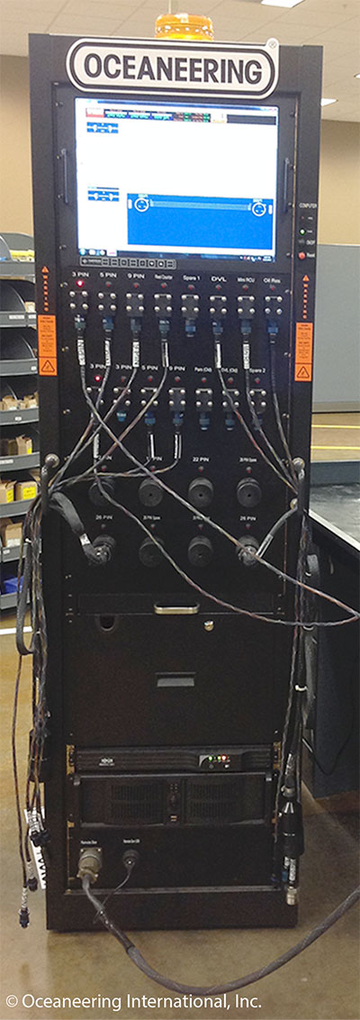
Fig. 4: Oceaneering International, Inc. (LA) - Mobile, rack-mounted, HiPot cable testing system for checking ROV cables.
Summary
Cables in motion experience fatigue causing complete or intermittent failures whether or not that motion is constant. We have seen that cable and harness test systems can easily identify and pinpoint the source of even the most elusive intermittent failure. Beyond continuity and resistance tests, diagnostic considerations for cables in motion are as follows:
- Test for intermittent faults.
- Test early in the workflow - ideally at your supplier’s site.
- Use a fast enough intermittence test cycle to provide statistically significant sampling.
- Mission-critical robots require a post-installation maintenance schedule that tests for intermittent errors.
CableEye ® Automation-Ready Cable and Wire Harness Test Systems
CableEye testers are highly versatile, expandable and upgradable diagnostic and Pass/Fail check Cable and Harness Test Systems that are PC-based. They are used for assembly, prototyping, production, and QC of standard or custom wire cables and harnesses The entire suite of products is powered by the same easy-to-use operating software and, with the help of its signature easy-to-interpret color-coded graphics, instantly identifies not only when there is a fault, but what type of fault and where.
Low Voltage M2 Series
For diagnostic and Pass/Fail Testing - Find, display, log, & document continuity (opens, shorts, miswires, intermittent connections).
Low Voltage M3 Series
For all of the above plus resistance (contact, isolation, embedded), and diodes (orientation, forward voltage, reverse breakdown).
Low Voltage M4 Series
For all of the above plus precision resistance (4-wire), and capacitance (twist wire relationship, length of cable, length to break, capacitors).
Low Voltage and High Voltage HVX Series
For all as described for M3 plus HiPot (dielectric withstand voltage and insulation resistance). 4-Wire Kelvin Measurement and Advanced Measurement Options (capacitance, twist wire relationship, length of cable, length to break, capacitors) are available.
Try One!
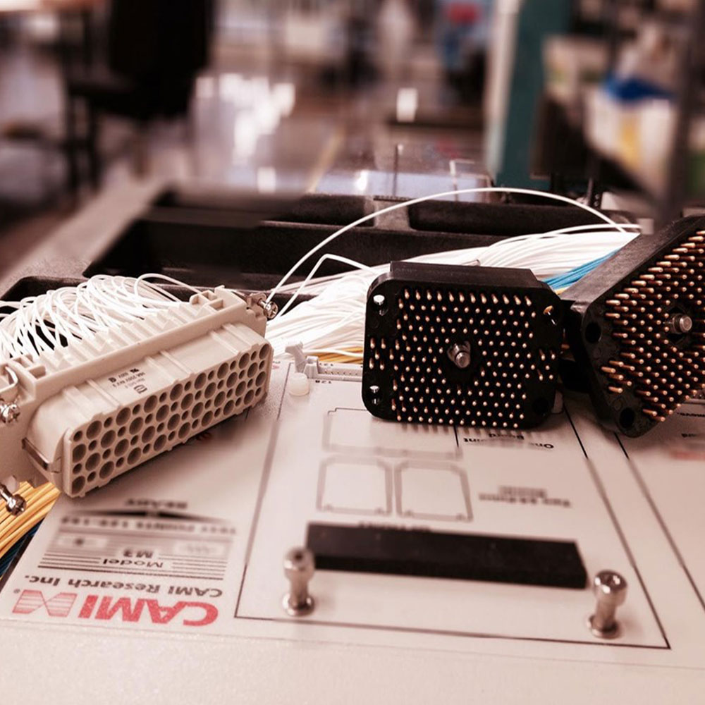
photo credit: Progressive Image
photo credit: AP Technology
"Our production guys find it simple to setup and use. Our clients love it as it provides complete traceability for each and every cable assembly we manufacture."
AP Technology, UK