Common Misconceptions in Testing Electrical Cables

Sample output from a CableEye cable tester.
Overview
With the exception of high-volume consumer products and automobiles, cable and wire harness assembly remains largely unyielding to automation. In a surprisingly large number of applications, the wiring of connectors to multiconductor cable demands the acuity of human vision and the dexterity of human hands. Some medical cables use wire so thin that it’s almost invisible and must be joined to connectors under a microscope, while other cables designed to carry very high frequency signals consist of multiple miniature coaxial conductors that must be wired to suitable connectors with great care to avoid introducing distortion or signal reflections.
While modern technology has come to the aid of assembly technicians tasked with this work by offering video guidance, light-fiber targeting of connector cavities, and immediate electrical feedback upon completing a good connection, fully automating the task continues to be beyond the reach of current robotics and software. Wherever an assembly task depends on human skill, assembly error remains a distinct possibility – people are not machines and, no matter how well trained a technician may be, occasional faults will creep in. Good assembly practice expects this and plans accordingly.
We detect assembly errors through testing. All testing begins with measurement. Once test results are obtained, comparing measured results against expected standards reveals faults.
The most likely fault in a cable assembly is the easiest and fastest to check: basic continuity. To do so, pass a current through one connector pin, and ensure that it reaches only the intended pins on other connectors. This reveals missing connections, short circuits, and miswired pins. However, this test alone does not provide the assurance that the wiring will operate correctly in it its expected application. Critically important are the quality of the connection between pins, and the isolation of conductors from each other. We can easily agree that these factors need to be proven in a thorough test. Unfortunately, our intuition may fail us when we try to set specific resistance thresholds for resistance or leakage limits for isolation. Several experiments described below will help to better understand the limits of fault detection in cables.
We will explore these limitations of continuity and HiPot testing, disproving three commonly held misconceptions outlined in the following table.

Connection Resistance
Resistance measurement tells us how competently a wire will carry its signal from one end to the other. The wire itself has an unavoidable natural resistance as a function of length and diameter. During assembly, we aim to eliminate additional resistance introduced by poor crimps, cold solder joints, or broken strands. Resistance testing tells us how successful we have been.
Typical 22-Gauge electrical wire has a natural resistance of about 16 mΩ/ft. (52 mΩ/m). A goldplated connector pin crimped to the wire will add a few milliohms to this depending on the contact area and crimp tightness. Alternatively, soldering the pin to the wire greatly increases the surface contact between the wire and pin offering negligible additional resistance on the order of a similar length of the wire itself.
Does soldering wires to pins (usually an expensive manual operation) provide a measurably better quality cable than crimping the pins (a frequently automated operation)? While it depends on the application, the answer is usually "No".
We then must ask “How low should the connection resistance be in an assembled cable?” which directly leads us to the question “Where, then, should we set the Pass/Fail threshold when testing wire a cable?” “50 mΩ, 0.5 Ω, 1 Ω, 5 Ω, 10 Ω, or something else?”
The answer depends primarily on how much current the wire is expected to carry. In Figure 1, the first circuit has no load. Because no current is flowing, there is no voltage drop across the wire resistance, and the voltage observed at the other end of the cable is unaffected by the wire resistance, regardless of the resistance value. In the second circuit, the load resistance equals the
wire resistance, current flows, with an equal voltage drop across the wire and the load.
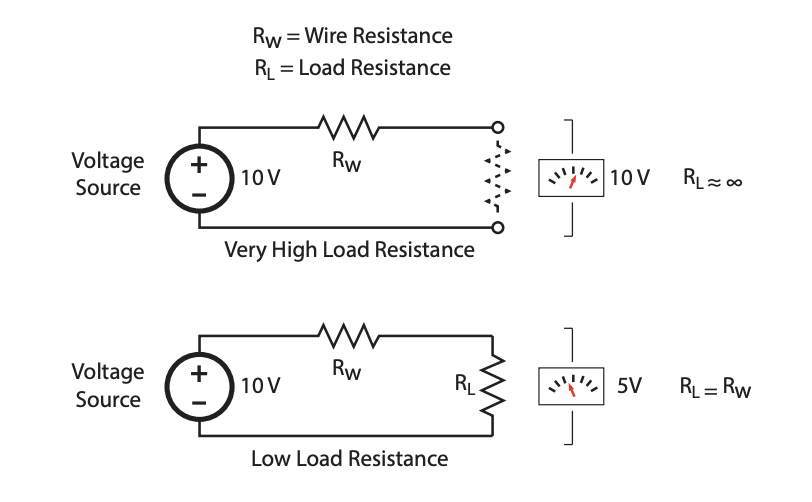
Fig. 1: How low should the connection resistance be in an assembled cable?
If the cable will drive an electronic device, such as a differential receiver with a 120 Ω terminating resistor, the load imposed on the cable will be minimal, and even relatively high conduction resistance values of 5 Ω or 10 Ω will not likely affect the signal, but still be low enough to overcome capacitive effects in the cable during high-speed digital switching.
If the cable were driving a relay coil, motor, or heating element, the load imposed on the cable will be significant, and low conduction resistance is critical to avoid device malfunction or heating in the cable. In this case, a threshold of 200 mΩ or less would be prudent. The cable’s designer should specify the test parameters with the expected worst-case load in mind to avoid the expense of overtesting with unnecessarily sensitive equipment, or the risk of undertesting with equipment incapable of setting a sufficiently low threshold.
As a rule of thumb, use a maximum resistance threshold of 1% of the expected load resistance. For the differential receiver cable discussed earlier, a 120 Ω load from the terminating resistor will be applied to the cable in its application, so we would want the maximum allowed cable resistance to not exceed 1 Ω and set the pass/fail threshold at 1 Ω. For loads of higher resistance (likely for electronic circuits), the threshold can be set proportionally higher, but generally not exceeding 10 Ω.
In summary, resistance measurements are essential in determining the quality of a connection and thus whether the connections are suitable for the intended application. This is true whether or not there are resistive elements embedded within the cable.
Crimp Faults
Quality managers concern themselves with various types of crimp faults that, in most cases, result in less than optimal surface contact between the wire and the pin. The most common faults result from an incorrectly adjusted wire stripping machine that takes off several strands of wire along with the insulation, or a crimping machine that captures part of the outer insulation under the crimp.
A visual inspection clearly shows these problems, however, visually inspecting crimps takes time and generally is not practical. Intuition suggests that a precise resistance test will find the problem. While theoretically true, resistance testing unfortunately does not provide a practical solution either. This experiment demonstrates why.
We connect 3.5” (8.9 cm) length of 22-gauge 7- strand wire, UL07-730, between two screw terminals, remove the insulation, and separate the strands. We will make milliohm resistance measurements with a CableEye ® 4-wire Kelvin measurement system. The strands will be cut, one-by-one, with resistor measurements made after each cut, to determine how the resistance varies with the number of intact strands. Figure 2 shows the setup.
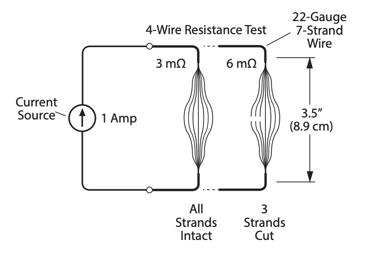
Fig. 2: Experiment for simulating and detecting crimp faults caused by cut strands.
This screen report from the CableEye tester (Fig. 3) shows the resistance with all but two strands cut (we are measuring between test points 50 and 56).
You can see from the table below how the resistance changes as strands are cut.
Interestingly, with only one strand remaining to carry the 1 A test current, no heating was detectable by human touch, although clearly the resistance increased slightly with the current applied for 1 second or longer compared to the initial short 50 ms dwell.
These results show that the resistance does increase slightly with each newly cut strand. However, to find 3 out of 7 strands cut, we need to detect a 3 mΩ increase in this 3.5" long wire. Unfortunately, variations in the contact resistance between the cable’s pins (one at each end of the wire) and the corresponding pins in the mating connector, and the natural wire resistance of cables longer than 3.5", swamp the tiny differences a few broken strands make. Variations in these pin contact resistances may easily change over a wider range than 3 mΩ without causing a cable to malfunction in its application. While we can detect these small differences in a laboratory setup, we cannot achieve a practical test for missing strands in a manufacturing environment.
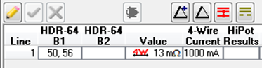
Fig. 3: Screen report showing resistance when only 2 of 7 strands are intact.

Table 1: Change in resistance as strands are cut.
In summary, although 4-wire Kelvin measurement is a more sensitive technique than standard two wire resistance testing, it still lacks the sensitivity to diagnose single-cut strands, single-stray strands, or crimp-caught insulation.
However, combining continuity, resistance, and intermittence testing with the use of appropriate test settings (wire resistance values, tolerances, dwell times etc.) provides confidence in the electrical integrity of the part backed with direct empirical evidence.
Isolation Resistance
A typical cable or wire harness has multiple insulated conductors bundled tightly together, possibly including a woven copper shield, and an outer insulating jacket. Ideally, current flowing through one wire should have no electrical effect on adjacent wires: no current would directly leak from one wire to another, and no induced current would result from capacitive coupling or electromagnetic interference. Limiting induced current comes largely through the design of the bulk cable by controlling insulation thickness and shielding and remains outside the control of the quality engineer. However, direct leakage between adjacent wires may well be caused by assembly defects in the connectors, or insulation containing pinholes, cuts, or other damage.
Applying voltage across unconnected wires will produce detectable current flow when various insulation faults exist. Such faults include moisture that has penetrated the connector body or insulation, excess solder flux or other contamination introduced during assembly, unterminated wire strands inside a connector from an improper crimp, conductive debris left inside a connector following assembly, or other defects resulting from uninsulated terminations being too close together inside a connector.
High voltage testing may reveal defects of excess leakage or insufficient air gap between conductors. We must ask, though, how much voltage should be applied and how big an air gap violation will it detect? The following experiment was conducted to test this and produced results that may be surprising.
A micrometer was securely mounted in a vice. A 30-gauge wire (0.01"/0.25mm diameter) is attached to the fixed end of the micrometer and held in place by insulated double-stick tape. This exposed wire remains fixed and completely flat against the micrometer's anvil. The positive side of the high voltage output drives this wire. The frame of the micrometer including the spindle (the movable part) is attached to ground.

Fig. 4: Experiment for simulating and detecting air gap violations.
As the spindle turns, the gap narrows, and the ground point moves closer to the positive wire. Each test starts with the spindle widely open (1 mm to 2 mm) and is gradually closed until a discharge occurs. We note the size of the gap at the moment of discharge. The experimental setup appears in Figure 4.
The wire represents a conductor with insulation damage, and the flat end of the spindle represents a grounded connector shell or another wire. At the time these measurements were made, the relative humidity was about 50%. In drier conditions, the discharge will occur at a slightly greater distance. The following table summarizes the results.
While high voltage testing provides a good test to confirm the quality of wire insulation, and detect moisture penetration or contamination, it cannot detect gap violations in excess of 0.006" (0.15 mm) at 1500 Vdc. To detect a pinhole opening in wire insulation, two wires would need to have overlapping pinholes and wire insulation in the thousands of an inch (not likely). A loose strand flailing around inside a connectors would need to be 0.006" away from another terminal to be detected by HiPot (possible but unlikely) and would better be found by an intermittent connection test while the cable is flexed.

Table 2: Air gap versus leakage current for a 30-gauge wire.
While our intuition would lead us to believe that a high voltage test will detect clearance violations and nicks in insulation, the detectable gaps using voltages of 2100 Vdc or less are far smaller than one might think. Using higher voltages to bridge wider gaps could pose an unsafe situation for the operator and may risk unintended collateral damage to insulation or otherwise good components.
In summary, insulation nicks and pinholes, and connectors that are too close together, can be detected with a high voltage test only under statistically unlikely conditions — conditions affected by a large number of variables that include fault size, alignment, spacing, humidity, and cleanliness. Detection is even less likely when nick and pinhole faults are in a single isolated wire. Creative test platforms could be employed to increase the likelihood of detection such as testing in an environmental chamber to optimize conditions for discharge.
Summary
Question your intuition. Oftentimes you should be checking resistance even if there are no resistors in your cable in order to check the quality of the connections. Yes, low resistance connections ensure good electrical connections in cables, but a cable’s application tells you where to set the Pass/Fail threshold. Setting it lower than you need to may create false positives, that is, failures against an unrealistic standard that wastes time and may lead to unnecessarily scrapped product. Setting the threshold too high, or not testing resistance at all, may permit product to reach its application with a time-bomb type of fault.
Cut strands or insulation-capture crimp errors prove highly undesirable but cannot be detected by production-practical resistance measurement. These problems will yield to improved production practices and possibly machine vision inspection of crimps. However, combining continuity, resistance, and intermittence testing with the use of appropriate test settings (wire resistance values, tolerances, dwell times etc.) provides confidence in the electrical integrity of the part backed with direct empirical evidence.
Insulation nicks and pinholes, and connectors that are too close together can be detected with a high voltage test only under statistically unlikely conditions. A lightening discharge can travel thousands of feet between clouds and ground when tens of millions of volts develop across that distance. Applying 1,500 V between two barewire conductors in a cable will not cause a discharge until the distance is reduced to less than half a millimeter (0.006"). No discharge or leakage will occur at conductor distances that are easily visualized unless the voltage used is high enough to cause hair to stand on end.
To learn more about the software that drives the CableEye tester referenced in this article, click the button below.
CableEye Testers for Checking Connection Resistance
With the exception of M2-series testers, all models of CableEye testers can be used to check the quality of good connections and good non-connections (i.e. isolation).
CableEye Testers with HiPot Capability
CableEye Testers with 4-Wire Measurement Capability
M4
4-Wire measurement capability with ±0.02 Ω resolution is a standard feature.
HVX Series
Advanced Measurements Option, Item 833, includes 4-wire measurement capability with ±0.02 Ω resolution. This option must be ordered at time of purchase of the control module.4-Wire Kelvin Resistance Measurement Option, Item 832, provides 4-wire measurement capability with ±0.001 Ω resolution. This option can be retrofitted.
CableEye ® Automation-Ready Cable and Wire Harness Test Systems
CableEye testers are highly versatile, expandable and upgradable diagnostic and Pass/Fail check Cable and Harness Test Systems that are PC-based. They are used for assembly, prototyping, production, and QC of standard or custom wire cables and harnesses The entire suite of products is powered by the same easy-to-use operating software and, with the help of its signature easy-to-interpret color-coded graphics, instantly identifies not only when there is a fault, but what type of fault and where.
Low Voltage M2 Series
For diagnostic and Pass/Fail Testing - Find, display, log, & document continuity (opens, shorts, miswires, intermittent connections).
Low Voltage M3 Series
For all of the above plus resistance (contact, isolation, embedded), and diodes (orientation, forward voltage, reverse breakdown).
Low Voltage M4 Series
For all of the above plus precision resistance (4-wire), and capacitance (twist wire relationship, length of cable, length to break, capacitors).
Low Voltage and High Voltage HVX Series
For all as described for M3 plus HiPot (dielectric withstand voltage and insulation resistance). 4-Wire Kelvin Measurement and Advanced Measurement Options (capacitance, twist wire relationship, length of cable, length to break, capacitors) are available.
Try One!
photo credit: Progressive Image
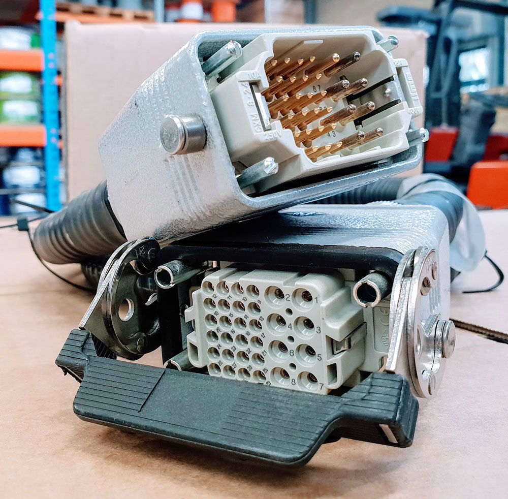
photo credit: AP Technology
"Our production guys find it simple to setup and use. Our clients love it as it provides complete traceability for each and every cable assembly we manufacture."
AP Technology, UK