
Testing Cables & Connectors in Medical Electronic Equipment and Devices
Overview
Smaller gauge wires are more difficult to insert, and combined with well-documented contact locking lance issues there is greater chance of continuity breaks especially when Connector and Terminal Position Assurance devices are neither features of the design nor of the chosen connector.
Testing continuity & HiPot using multiconductor cable testers is an essential part of the workflow. Thorough testing prior to and after installation reduces the likelihood of device failure including catastrophic events such as fire. It is simply not sufficient to rely on “glow-wire” specifications to prevent fire. In this article we introduce a basic understanding of what ‘thorough’ continuity and HiPot testing entails.
Continuity Test
The traditional basic continuity test checks for opens and shorts at an instant in time only. The limitation of the traditional approach is that the result is only true for the test object as it was presented in physical location/orientation at that instant. Let’s consider a connectorized cable. If such a test was performed yielding a ‘PASS’, it cannot be assumed that the same would hold true when the cable is moved to other points
The danger is that companies relying on the Traditional Test are at risk of installing defective cables in their equipment. This results, at best, in equipment failures that frustrate the end-user and, at worst, in a major malfunction or catastrophic event such as a fire or loss of life-support that could result in death.
To check continuity thoroughly, an enhanced test should be performed that additionally scans for both intermittent and miswire errors (Table 1).
| Checks | Traditional | Enhanced | Opens |
|---|---|---|
| Shorts | ||
| Miswires | ||
| Intermittent Faults |
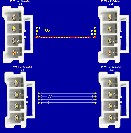
a) Continuity test result (top) and b) golden cable (bottom). Test result overlays desired design, and highlights type and location of error - open (yellow), miswire (yellow-red striped). Note: A short, if present, would show as a solid red line.
*All sreenshots from CableEye® test system, courtesy of CAMI Research.
Connector pins that are not fully seated cause intermittent opens, while conductive debris is often the source of intermittent shorts, especially with micro-pitch connectors. These faults might cause intermittent power disruption to a motor resulting in motor damage, or signal a solenoid to switch the wrong valve or the right valve at the wrong time perhaps delivering the wrong dosage to a patient.
The same test process can be used to verify board-to-board connectors with floating designs with the intermittence test being performed while the connector is moved through its full adjustment range. Design verification data (http://suddendocs.samtec.com/testreports/tc1023--3438_report_rev_2.pdf) suggest that between 2 and 9 lbs force is needed to move these connectors to their maximum range. The motion could be applied manually or through a motorized jig for improved repeatability.
In short, I really appreciate the capabilities the CableEye system brings, especially the versatility. It was a delight using the CableEye tester and I am looking forward to using it more. Thank you for a great product!
Precision Interconnect Solutions
High Voltage Tests
Insulation integrity is verified with High Voltage (HV) tests and can be carried out with ac or dc voltages. In either case, the test calls for the applied voltage to far exceed the specified operating voltage. For safety reasons, HV tests are applied only after successful completion of continuity testing. Testers such as the CableEye HVX series perform both categories of tests and can be programmed to automatically and seamlessly switch from one to the other. These HV tests consist of checking the Dielectric Withstand Voltage (DWV) and the Insulation Resistance (IR) and reveal design and manufacturing faults such as insulation pinholes and the presence of gap-bridging moisture. A passing device will be proven to have insulation capable of protecting the end-user even during power surges.
The same HV tests can also highlight issues with the sharing of signal and power lines within the same connector, and within connectors of compact pitch.
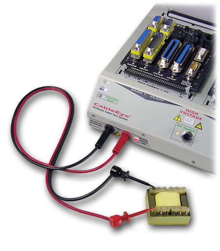
2 – From Single Channel to Multiconductor
Modern PC-based cable testers can readily switch between testing components (such as chassis, panels, transformers) and multiconductor cables & harnesses - and for voltages up to 2100Vdc/1200Vac. Figure 5 depicts a transformer under test with a screenshot of the near instantaneous result – DWV (1015 V), Leakage Current (212 µA), IR (5 MΩ). Leakage current measurements are especially useful when determining whether borderline DWV or IR results are really an issue. The same user interface appears and test principles apply when HV-testing multiconductor set-ups. In this case, the cables connect to the tester via interface boards (such as seen in Figs. 1 and 5), or via interface ‘harnesses’ such as an Ampmodu cable.
In-Plant Scenarios
Thorough testing of a product starts at the Design Verification and Prototyping phases. Early feedback of the results allows for improved Design for Manufacturability and saves money by catching problems sooner in the workflow.
Typically, harnesses and cables destined for systems such as Medical Equipment and Devices are tested within an environmental chamber where the rigors of transportation and a life of operation in a variety of operational temperatures, humidity, and vibration can be simulated. These tests cover aspects of safety, reliability, and accelerated aging.
The same PC-based testers used for Continuity and HV tests on the production line are flexible enough to be integrated into these test systems, and can accommodate long test interfaces between the tester and environmental chamber electrical ports (to which the cables under test within the chamber are connected).
The prototyping stage is also prime time to develop test automation processes for the production line.
2 – Test Automation
For efficient testing, many manufacturing engineers prefer to automate Continuity and HV testing. With PC-based testers, they are able to incorporate external relay boards to automatically switch between different circuits during test, or to operate lock & release latches; use API or LabView interfaces to integrate with other equipment; scan ID badges for operator log-in; scan work orders for automatic tester set-up; connect foot pedal or remote controls and a variety of audible and visual Pass/Fail external indicators (such as tower lights).
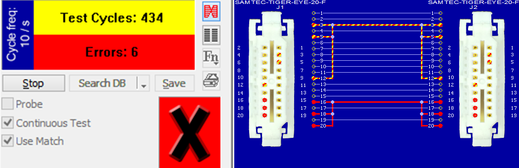
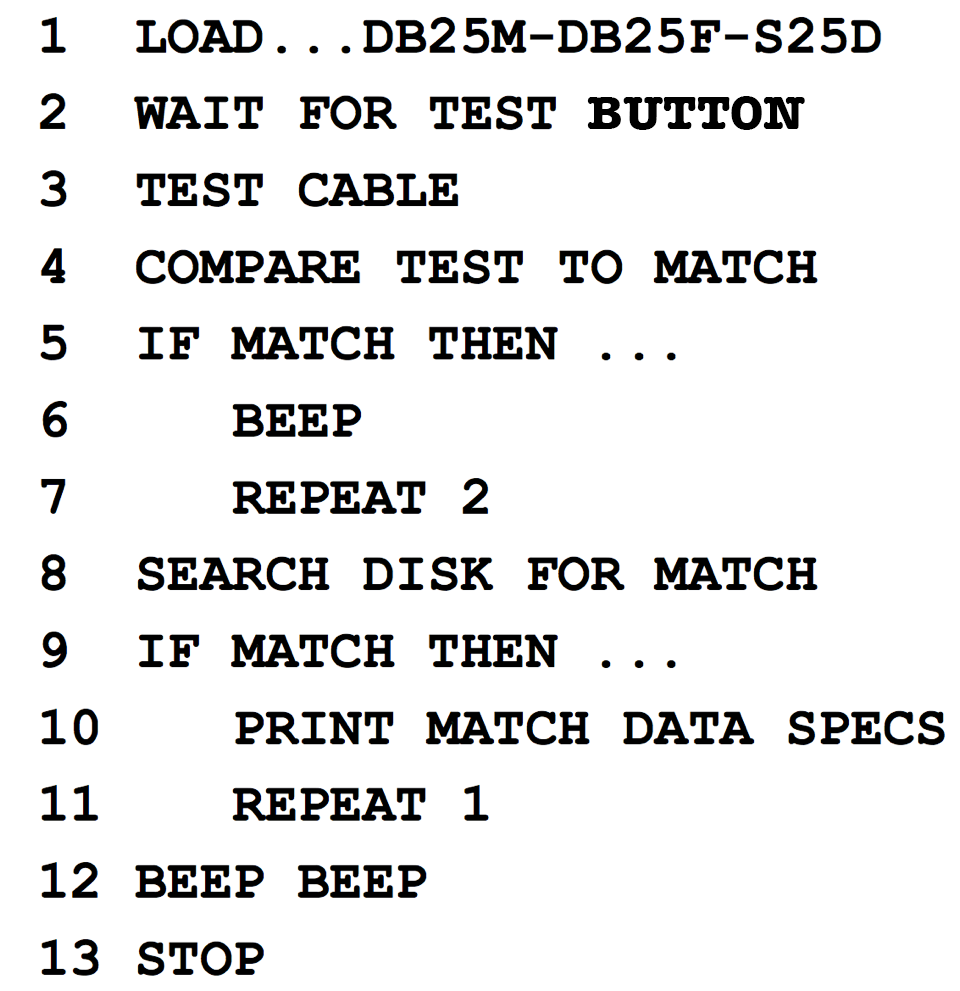
The test procedure itself is written in a simple scripting language and includes calls to automatically log the test data for statistical process control, and to print graphical test reports for internal or customer use. An example of this procedure, a macro, is given in Fig. 6 that can be triggered by the in-built test pushbutton, or a peripheral such as a footswitch, or relay closure.
Summary
Modern electronic equipment is calling for smaller volume electrical designs yet with greater functionality, resulting in systems that must be more carefully checked for continuity and insulation integrity – incorporation of smaller pitch connectors brings a higher chance of faults.
An enhanced continuity check has been discussed that tests for opens, shorts, miswires, and intermittent faults, and high voltage tests to check insulation integrity were described. The same HV tests can also highlight issues with the sharing of signal and power lines within the same connector, and within connectors of compact pitch.
PC-Based Cable Testers are well suited to the thorough testing required for Medical Equipment cables and connectors, including for design verification, prototyping, and automation.
To learn more about the software that drives CableEye testers, click the button below.
CableEye ® Automation-Ready Cable and Wire Harness Test Systems
CableEye testers are highly versatile, expandable and upgradable diagnostic and Pass/Fail check Cable and Harness Test Systems that are PC-based. They are used for assembly, prototyping, production, and QC of standard or custom wire cables and harnesses The entire suite of products is powered by the same easy-to-use operating software and, with the help of its signature easy-to-interpret color-coded graphics, instantly identifies not only when there is a fault, but what type of fault and where.
Low Voltage M2 Series
For diagnostic and Pass/Fail Testing - Find, display, log, & document continuity (opens, shorts, miswires, intermittent connections).
Low Voltage M3 Series
For all of the above plus resistance (contact, isolation, embedded), and diodes (orientation, forward voltage, reverse breakdown).
Low Voltage M4 Series
For all of the above plus precision resistance (4-wire), and capacitance (twist wire relationship, length of cable, length to break, capacitors).
Low Voltage and High Voltage HVX Series
For all as described for M3 plus HiPot (dielectric withstand voltage and insulation resistance). 4-Wire Kelvin Measurement and Advanced Measurement Options (capacitance, twist wire relationship, length of cable, length to break, capacitors) are available.
Try One!
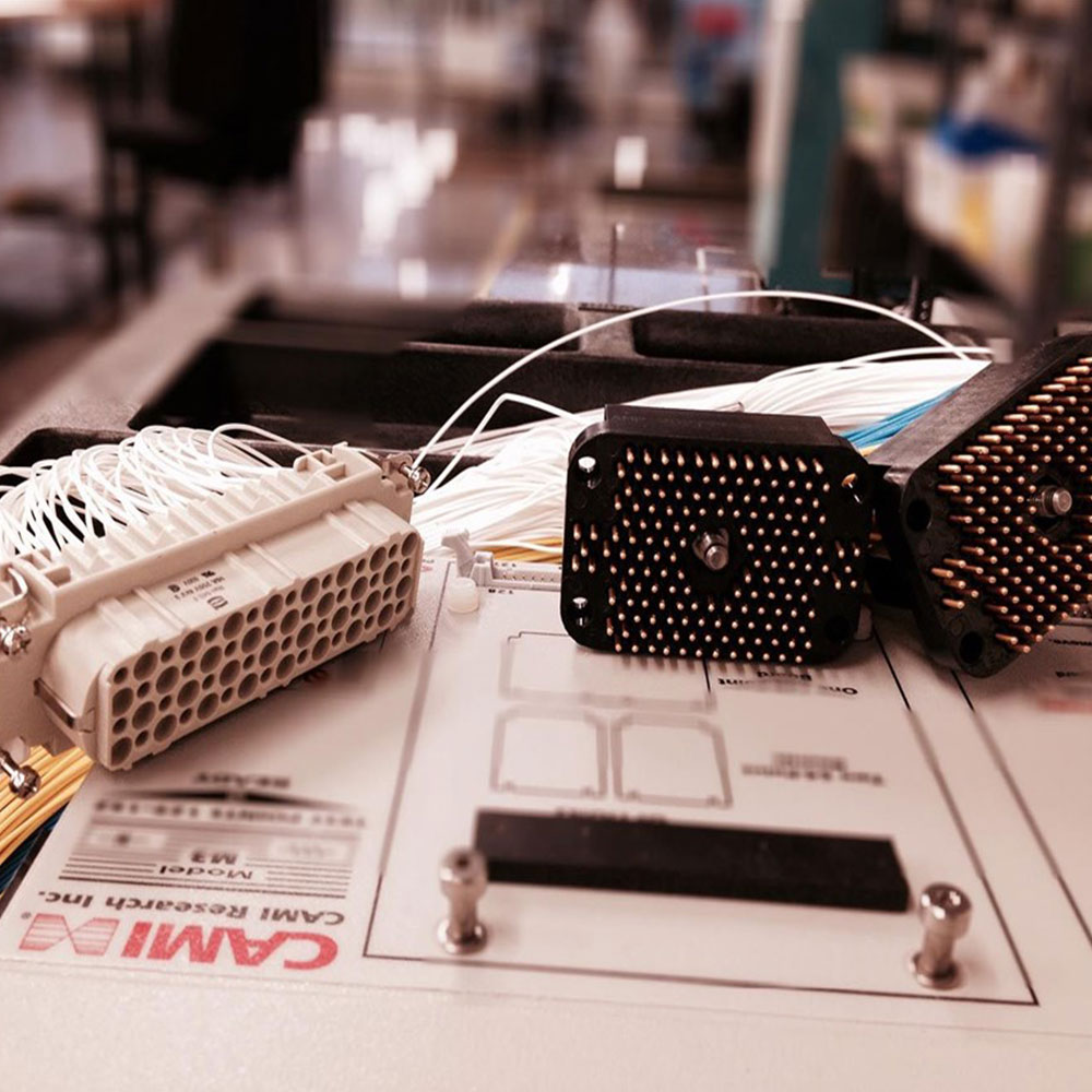
photo credit: Progressive Image
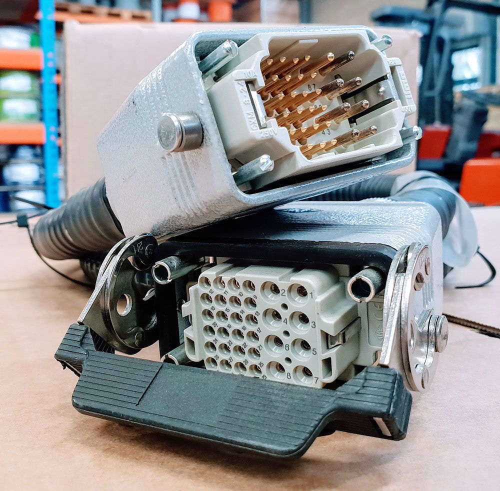
photo credit: AP Technology
"Our production guys find it simple to setup and use. Our clients love it as it provides complete traceability for each and every cable assembly we manufacture."
AP Technology, UK