Verifying Twist Pair Relationships with a Continuity Tester

Overview
In this article, we discuss testing of twisted pair cables and why a twisted cable that passes continuity alone is not a fail-safe indicator that wire twists are wired correctly. We show which twist errors can be detected with a simple continuity test, and which require a twist wire measurement.
The greater the number of twisted pairs in a cable, the greater the probability of a mis-twist error during connectorization. Many combinations of such miswiring can be caught with a simple continuity test. However, some cannot. A mis-twisted wire that passes a continuity test will experience faulty signal transmission during its intended operation. To guarantee proper wiring, a twist pair relationship test should be carried out.
Although Ethernet cables are described within, note that multiconductor continuity testers (such as CableEye® units) will measure twisted pairs – and even triplets - in any cable.
Without performing these checks, you run the risk of releasing or accepting faulty product. It is important to know and understand the parameters against which your cable or harness has been judged to have “passed”.
Twisted Pair Measurement
1 – Why Bother?
Twisted pair wires of the type found in Ethernet cables provide a low-cost approximation of coaxial cable. The more twists per foot, the higher the Category number (as in Cat 5 or Cat 6) of the cable, the more it appears like a coaxial cable, and the more faithfully it carries the signal without distortion.
Unlike coaxial cables, however, twisted pair cables can be “mistwisted”, leading to incorrect signal transmission. Normally, for each signal line, a complementary signal line winds around it to create one pair.
Typically, an Ethernet cable contains four pairs and should be wired +Signal1/-Signal1, +Signal2/- Signal2, etc. If, through miswiring, we have two pairs in the cable wired +Signal1/+Signal2 and - Signal1/-Signal2, the cable will be faulty and unusable.
Unfortunately, this type of error cannot be determined by continuity measurements alone – the continuity would look correct for either twist arrangement.
Note that to arrive at an erroneous twist relationship like this, an identical assembly error would need to be made at each end of the cable, certainly an unlikely scenario. Nonetheless, manufacturers and cable assembly shops need to ensure that the pairs are twisted correctly. We accomplish this by means of capacitance measurement.
Capacitance measurements acquired during the twist pair check on reels and cables are auto-saved and can be used to verify reel-to-reel and cable- to-cable consistency and quality. Ideally, your tester will log all connection measurements for record keeping and analysis.
2 – Mistwist Scenarios
In one twisted pair, the two wires involved come much closer to each other (two insulation thicknesses) than they do to adjacent pairs. As a result, the capacitance of a twisted pair would be expected to be higher than the capacitance between other wires in the cable (Fig. 1), and with this information, we can determine the necessary relationship.
The Netlist for the measurement of an Ethernet cable (i.e. four twisted pairs) is shown in Fig. 2.
Examples of one and two wiring error scenarios are shown in Figs. 3 and 4. Twisted-Pair cable with TWO wiring errors will PASS a Continuity Test and twisted-pair capacitance measurement is necessary to detect the error.
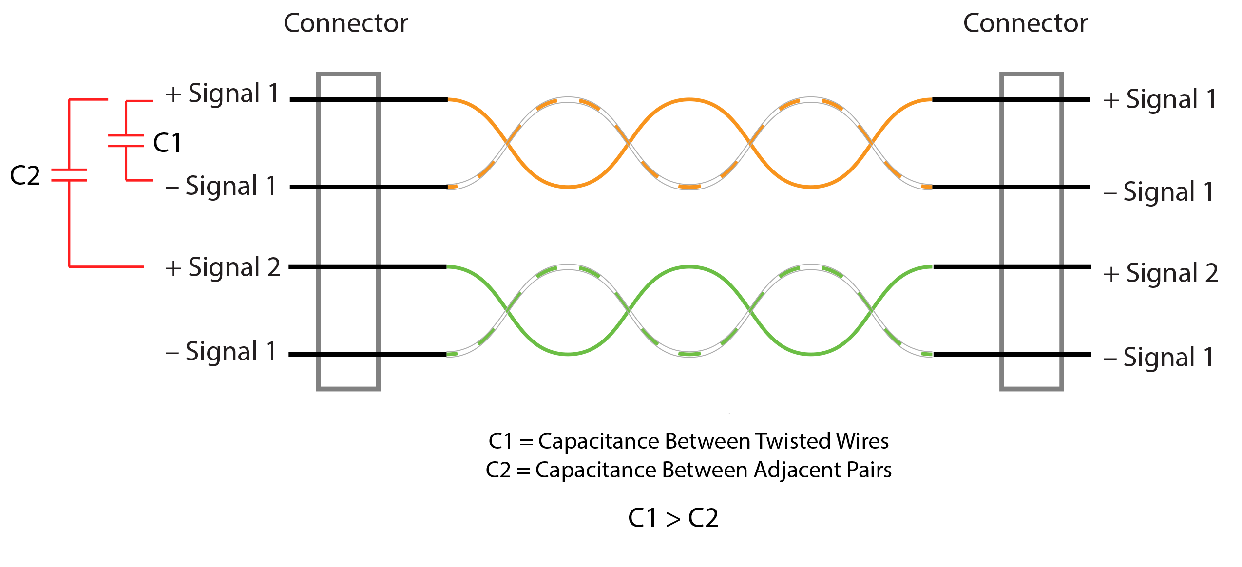
Fig. 1: Capacitance Relationship in a Correctly Wired Twisted-Pair Cable

Fig. 2: Measurement of Four Twisted Pairs of an Ethernet Cable: The first two columns list the pin order on the connector, and the "Pair" column identifies the pairing.

Fig. 3: Twisted-Pair Cable with One Wiring Error: This will fail a continuity test, therefore twisted-pair capacitance measurement is unnecessary to detect the error.


Pair Error Indicator
Fig. 4: Twisted-Pair Cable with TWO Wiring Errors will PASS a Continuity Test: Twisted-Pair Capacitance measurement is necessary to detect the error as shown. Here you see pins 1 and 2 have been swapped creating a pairing error as shown in this CableEye screen image.
Testing Twisted Pair Cables
1 – What does ‘Pass’ mean?
The PASS indicator on a twisted-pair test (Fig. 5) shows that the wire resistances comply with the threshold and that the wires are paired correctly. If you’ve entered a capacitance value in the Match Data as well as a tolerance, then the values shown in the Test Data are within your preset tolerance.
2 – Cable Length
When connecting both ends of a cable to the tester, the minimum length to acquire proper pairing for unshielded Ethernet cable is about 6 feet. For shielded Ethernet cable, the minimum length becomes a couple of feet longer because the shield couples with the internal wires.

Fig. 5: Netlist View of a “Pass”: An Ethernet cable that has Passed Continuity and Twist
3 – Test Sequence
Resistance measurements are made before those of pairing and capacitance. When a conductor resistance exceeds the current resistance threshold, pairing and capacitance measurement will not be made on that conductor, and the cable will fail for reason of excessive resistance (Fig. 6). When resistances are acceptable, the tester automatically moves on to check and measure pairing and capacitance.
4 – Crossover Ethernet Cable
The conductor order we have discussed applies to straight-through Ethernet cable. For crossover Ethernet cable, the conductor order will be different, but the pairing will be the same as viewed from one side of the cable (Fig. 7).

Fig. 6: Detection of Excessive Resistance Halts Testing (Line 2).


Fig. 7: Crossover Ethernet Cable Wiring and Netlist
5 – Wire Type
Although Ethernet cables are described in the examples, the testers described here will measure twisted pairs – and even triplets - in any cable you test.
6 – Wire Mix
When there is mix of wire types within a cable (i.e. when only some are twisted pairs), prior to testing, simply define pairs in the Match Data only for those wires that are twisted (Fig. 8).

Fig. 8: This test result used Match Data with conductors 1 and 2 having no entry in the pair column.
Summary
We have discussed testing twisted pair cables and shown why a twisted cable that passes continuity alone is not a fail-safe indicator that wire twists are wired correctly.
Multiconductor continuity testers can test twisted pair cables to check for correct twist pair relationships. A PASS indicator shows that the wire resistances comply with the threshold AND that the wires are paired correctly. If a target capacitance value and tolerance has been entered, then the values shown in the Test Data are within the capacitance tolerance.
This method can also be used to verify spool to spool consistency of wire twist quality.
To learn more about the software referenced in this article, click the button below.
CableEye Testers for Verifying Twist Pair Relationships
Choose CableEye model M4, or any HVX-series tester fitted with the Advanced Measurements option.
CableEye ® Automation-Ready Cable and Wire Harness Test Systems
CableEye testers are highly versatile, expandable and upgradable diagnostic and Pass/Fail check Cable and Harness Test Systems that are PC-based. They are used for assembly, prototyping, production, and QC of standard or custom wire cables and harnesses The entire suite of products is powered by the same easy-to-use operating software and, with the help of its signature easy-to-interpret color-coded graphics, instantly identifies not only when there is a fault, but what type of fault and where.
Low Voltage M2 Series
For diagnostic and Pass/Fail Testing - Find, display, log, & document continuity (opens, shorts, miswires, intermittent connections).
Low Voltage M3 Series
For all of the above plus resistance (contact, isolation, embedded), and diodes (orientation, forward voltage, reverse breakdown).
Low Voltage M4 Series
For all of the above plus precision resistance (4-wire), and capacitance (twist wire relationship, length of cable, length to break, capacitors).
Low Voltage and High Voltage HVX Series
For all as described for M3 plus HiPot (dielectric withstand voltage and insulation resistance). 4-Wire Kelvin Measurement and Advanced Measurement Options (capacitance, twist wire relationship, length of cable, length to break, capacitors) are available.
Try One!
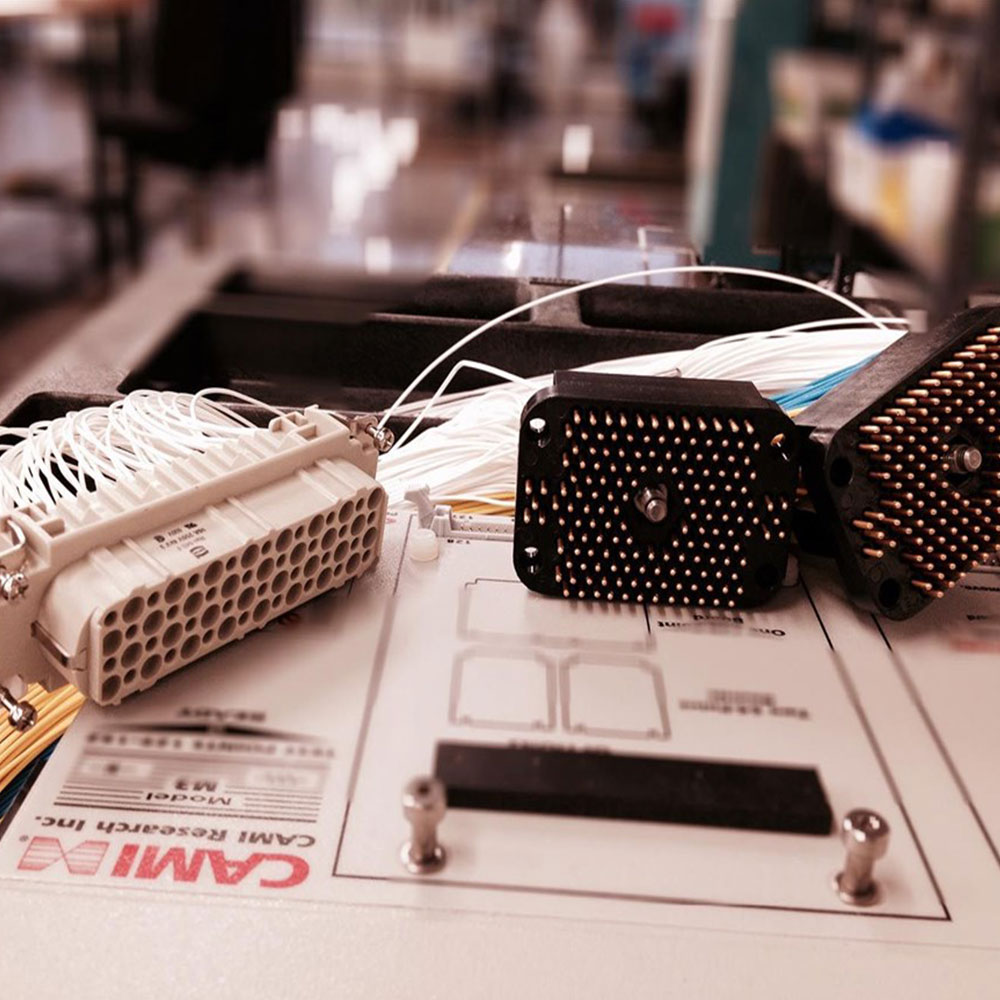
photo credit: Progressive Image
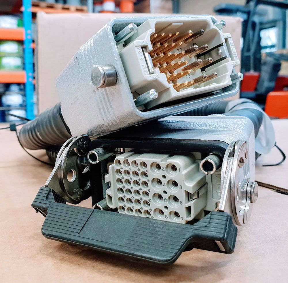
photo credit: AP Technology
"Our production guys find it simple to setup and use. Our clients love it as it provides complete traceability for each and every cable assembly we manufacture."
AP Technology, UK